Sélection de la langue

Search

Sommaire du brevet 2056567 

Énoncé de désistement de responsabilité concernant l'information provenant de tiers

Une partie des informations de ce site Web a été fournie par des sources externes. Le gouvernement du Canada n'assume aucune responsabilité concernant la précision, l'actualité ou la fiabilité des informations fournies par les sources externes. Les utilisateurs qui désirent employer cette information devraient consulter directement la source des informations. Le contenu fourni par les sources externes n'est pas assujetti aux exigences sur les langues officielles, la protection des renseignements personnels et l'accessibilité.

Disponibilité de l'Abrégé et des Revendications

L'apparition de différences dans le texte et l'image des Revendications et de l'Abrégé dépend du moment auquel le document est publié. Les textes des Revendications et de l'Abrégé sont affichés :

  • lorsque la demande peut être examinée par le public;
  • lorsque le brevet est émis (délivrance).
(12) Brevet: (11) CA 2056567
(54) Titre français: GENERATRICE D'ALLUMAGE A GRANDE PUISSANCE, PARTICULIEREMENT POUR UNE TURBINE A GAZ
(54) Titre anglais: HIGH ENERGY IGNITION GENERATOR IN PARTICULAR FOR A GAS TURBINE
Statut: Périmé
Données bibliographiques
(51) Classification internationale des brevets (CIB):
  • F02P 3/08 (2006.01)
  • F02C 7/266 (2006.01)
  • F02P 15/00 (2006.01)
  • H03K 3/57 (2006.01)
  • H03K 4/02 (2006.01)
(72) Inventeurs :
  • BALLAND, PATRICK GUY ANDRE (France)
(73) Titulaires :
  • VIBRO METER FRANCE (France)
(71) Demandeurs :
(74) Agent: NORTON ROSE FULBRIGHT CANADA LLP/S.E.N.C.R.L., S.R.L.
(74) Co-agent:
(45) Délivré: 1995-11-21
(22) Date de dépôt: 1991-11-28
(41) Mise à la disponibilité du public: 1992-06-20
Requête d'examen: 1991-11-28
Licence disponible: S.O.
(25) Langue des documents déposés: Anglais

Traité de coopération en matière de brevets (PCT): Non

(30) Données de priorité de la demande:
Numéro de la demande Pays / territoire Date
90 15 944 France 1990-12-19

Abrégés

Abrégé anglais


The generator comprises a source of energy provided with
a transformer (104) whose secondary winding is connected to
a first circuit comprising a capacitor (106), an inductor
(107) and an ignition spark plug (108) connected in series,
and means (109) for shorting the first circuit so as to
produce sparks between the electrodes of the spark plug
(108), comprising at least a semi-conductor switching means
controlled by means (110) for comparing the voltage at the
terminals of the capacitor (106) with a reference voltage
and means for controlling the charge of the capacitor,
interposed between the source of energy and the first
circuit, is characterized in that the comparing means (110)
are connected to the terminals of a capacitor (111) of a
second circuit connected to the terminals of another
secondary winding (114) of the transformer (104), this
second circuit being equivalent to the first circuit so that
the voltage at the terminals of the capacitor (111) of the
second circuit is the image of the voltage at the terminals
of the capacitor (106) of the first circuit.

Revendications

Note : Les revendications sont présentées dans la langue officielle dans laquelle elles ont été soumises.


- 6 -


The embodiments of the invention in which an exclusive property
or privilege is claimed are defined as follows:
1. High energy ignition generator comprising a source
of energy provided with a transformer having a secondary
winding, a first circuit connected to said secondary winding
and comprising in series an energy storage capacitor, an
inductor and an ignition spark plug, a free wheel diode
being connected in parallel to the terminals of said
inductor and said ignition spark plug, and means being
provided for shorting said first circuit so as to produce
sparks between the electrodes of said spark plug, said
shorting means comprising at least semi-conductor switching
means, means for controlling said switching means, said
means for controlling said switching means being operative
to compare the voltage at the terminals of said storage
capacitor with a reference voltage, means being interposed
between said source of energy and said first circuit for
controlling the charging of said capacitor at a first rate
during a first period of time and at a second rate during a
second period of time, said second rate being higher than
said first rate, said generator further comprising a second
secondary winding of said transformer, a second circuit and
a second capacitor, said means for comparing the voltage at
the terminals of said capacitor of said first circuit with
said referece voltage being connected to the terminals of
said second capacitor, said second circuit comprising in
series at least said second capacitor and impedance means
connected to the terminals of said second secondary winding


- 7 -


of said transformer, said second circuit being equivalent to
said first circuit so that the voltage at the terminals of
said second capacitor is the image of the voltage at the
terminals of said capacitor of said first circuit.
2. Generator according to claim 1, wherein said
impedance means comprise an inductor.
3. Generator according to claim 1, wherein said
impedance means comprise a resistor.
4. Generator according to claim 1, wherein said
impedance means comprise an inductor and a resistor.
5. Generator according to claim 1, comprising means
connected to the terminals of said second capacitor for
discharging said second capacitor .
6. Generator according to claim 5, wherein said means
for discharging said second capacitor comprise a resistor.
7. Generator according to claim 6, wherein said
comparing means are connected to said source of energy for
controlling the frequency of said sparks in accordance with
the value of said resistor for discharging said second
capacitor.


Description

Note : Les descriptions sont présentées dans la langue officielle dans laquelle elles ont été soumises.

2~5~567


HIGE~ ENERGY IGNITION GENERATOR
IN PARTICULAR FOR A GAS TURBINE
The present invention relates to an improvement in the
high energy ignition generator in particular for a
gas turbine disclosed in the French patent application
No. 88 12 272 in the name of the Applicant.
This patent application discloses a high energy ignition
generator of the type comprising a power supply provided
with a transformer whose secondary winding is connected to a
first circuit comprising an energy storage capacitor, an
inductor and an ignition spark plug, in series, a free wheel
diode being connected in parallel to the terminals of the
inductor and the ignition spark plug and means for shorting
the first circuit in such manner as to produce sparks
between the electrodes of the spark plug, wherein the
shorting means comprise at least one semi-conductor
switching means controlled by means for comparing the
voltage at the terminals of the storage capacitor with a
reference value and means for controlling the charging of

the capacitor at a first rate during a first period of time
and at a second rate during a second period of time, the
second rate being higher than the first rate, are interposed
between the power supply and the first circuit.
In the embodiment disclosed in said patent application,

the means for comparing the voltage at the terminals of the
capacitor of the first circuit with the reference voltage
are directly connected to the terminals of this capacitor.

~ 2~56557


This results in a number of drawbacks in that it is
necessary to provide a secondary power supply for these
comparing means and there is no galvanic insulation between
these two parts of the generator.
An object of the invention is therefore to overcome
these problems by providing an embodiment of this generator
which permits galvanically insulating these two parts of the
latter and is simple and reliable.
The invention therefore provides a generator such as

that described hereinbefore, characterized in that the means
for comparing the voltage at the terminals of the capacitor
of the first circuit with the reference voltage are
connected to the terminals of a capacitor of a second
circuit comprising in series at least said capacitor and
impedance means connected to the terminals of another
secondary winding of the transformer, said second circuit
being equivalent to the first circuit so that the voltage at
the terminals of the capacitor of the second circuit is the
image of that at the terminals of the capacitor of the first
circuit.
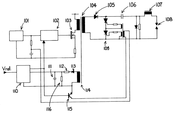
A better understanding of the invention will be had from
the following description which is given solely by way of
example with reference to the accompanying drawing which
represents a schematic diagram of a generator according to

the invention.
This diagram shows the general structure of a generator
such as that disclosed in said patent application the


2~)5~;567


details of which application are included in this
specification by reference.
This generator comprises a source of energy comprising a
power supply 101 for triggering through an excitation
circuit 102 a transistor 103 for feeding the primary winding
of a transformer 104 which is equivalent to the transformer
7 disclosed in said patent application.
A first secondary winding of this transformer is
connected to a first circuit comprising in series a diode


105, an energy storage capacitor 106, an inductor 107 and an
ignition spark plug 108.
Means 109 for shorting this first circuit are also
provided to produce sparks between the electrodes of the
spark plug.
These shorting means have a structure similar to that of
the equivalent means disclosed in said patent application
and comprise at least one semi-conductor switching means
controlled by means 110 for comparing the voltage at the
terminals of the capacitor 106 of the first circuit with a
reference voltage.
The excitation circuit 102 permits controlling the
charging of the capacitor 106 of the first circuit at a
first rate during a first period of time and at a second
rate during a second period of time, the second rate being


higher than the first rate, as explained in said patent
application.
While in the embodiment disclosed in said patent

~C! 5S567


application the voltage at the terminals of the capacitor
106 of this first circuit is taken directly from the
terminals of this capacitor, in the embodiment accordiny to
the present invention this voltage is taken from the
terminals of a capacitor 111 of a second circuit comprising
in series at least this capacitor 111 and an impedance 112
comprising for example a resistor and/or an inductor
operating as a function of the operating frequency. This
second circuit is connected through a diode 113 to the

terminals of a second secondary winding 114 of the
transformer 104. This second circuit is equivalent from the
electrical point of view to the first circuit so that the
voltage at the terminals of the capacitor 111 of the second
circuit is the image of that at the terminals of the
capacitor 106 of the first circuit.
Indeed, as the load of the transformer is essentially
capacitive, the output voltage of the first winding of this
transformer is at each instant equal to the charging voltage
of the capacitor of the first circuit. In the case where

the second circuit is equivalent from the electrical point
of view to the first circuit, the voltage at the terminals
of the capacitor of this second circuit is therefore the
image of the voltage at the terminals of the capacitor of
the first circuit so that it is possible to employ indirect
means for obtaining the voltage at the terminals of the
capacitor of the first circuit while achieving a galvanic
insulation of these two parts of the generator.

2~567
-


The output of the comparing means 110 is employed, in amanner sirnilar to that disclosed in said patent application,
for controlling the shorting means 109, for example through
a transistor 115, and can also be employed for controlling
the excitation circuit 102 of the source of energy feeding
the primary winding of the transformer for determining the
frequency of the sparks in that, as the charge of the
capacitor 111 is known, it is possible to obtain a time base
permitting the determination of the frequency of the sparks.

Indeed, the capacitor 111 must be discharged after each
spark and means for discharging this capacitor are provided
at the terminals of the latter. These means may for example
consist of a transistor of known type or a resistor 116.
The discharging of the capacitor 111 into the resistor 116


permits obtaining the aforementioned time base and the value
of this resistor may be so chosen as to obtain a given spark
frequency.
The general operation of this device is similar to that
described in said patent application and therefore need not

be described in more detail.

Dessin représentatif
Une figure unique qui représente un dessin illustrant l'invention.
États administratifs

Pour une meilleure compréhension de l'état de la demande ou brevet qui figure sur cette page, la rubrique Mise en garde , et les descriptions de Brevet , États administratifs , Taxes périodiques et Historique des paiements devraient être consultées.

États administratifs

Titre Date
Date de délivrance prévu 1995-11-21
(22) Dépôt 1991-11-28
Requête d'examen 1991-11-28
(41) Mise à la disponibilité du public 1992-06-20
(45) Délivré 1995-11-21
Expiré 2011-11-28

Historique d'abandonnement

Il n'y a pas d'historique d'abandonnement

Historique des paiements

Type de taxes Anniversaire Échéance Montant payé Date payée
Le dépôt d'une demande de brevet 0,00 $ 1991-11-28
Enregistrement de documents 0,00 $ 1992-07-21
Taxe de maintien en état - Demande - nouvelle loi 2 1993-11-29 100,00 $ 1993-10-12
Taxe de maintien en état - Demande - nouvelle loi 3 1994-11-28 100,00 $ 1994-10-28
Taxe de maintien en état - Demande - nouvelle loi 4 1995-11-28 100,00 $ 1995-10-18
Taxe de maintien en état - brevet - nouvelle loi 5 1996-11-28 150,00 $ 1996-10-18
Taxe de maintien en état - brevet - nouvelle loi 6 1997-11-28 150,00 $ 1997-10-17
Enregistrement de documents 50,00 $ 1998-02-02
Taxe de maintien en état - brevet - nouvelle loi 7 1998-11-30 150,00 $ 1998-10-21
Taxe de maintien en état - brevet - nouvelle loi 8 1999-11-29 150,00 $ 1999-11-22
Taxe de maintien en état - brevet - nouvelle loi 9 2000-11-28 150,00 $ 2000-11-17
Enregistrement de documents 50,00 $ 2001-01-26
Taxe de maintien en état - brevet - nouvelle loi 10 2001-11-28 200,00 $ 2001-11-09
Taxe de maintien en état - brevet - nouvelle loi 11 2002-11-28 200,00 $ 2002-11-13
Taxe de maintien en état - brevet - nouvelle loi 12 2003-11-28 200,00 $ 2003-11-14
Taxe de maintien en état - brevet - nouvelle loi 13 2004-11-29 250,00 $ 2004-11-17
Taxe de maintien en état - brevet - nouvelle loi 14 2005-11-28 250,00 $ 2005-11-18
Taxe de maintien en état - brevet - nouvelle loi 15 2006-11-28 450,00 $ 2006-11-24
Taxe de maintien en état - brevet - nouvelle loi 16 2007-11-28 450,00 $ 2007-10-19
Taxe de maintien en état - brevet - nouvelle loi 17 2008-11-28 450,00 $ 2008-10-24
Enregistrement de documents 100,00 $ 2009-05-11
Taxe de maintien en état - brevet - nouvelle loi 18 2009-11-30 450,00 $ 2009-10-22
Taxe de maintien en état - brevet - nouvelle loi 19 2010-11-29 450,00 $ 2010-10-15
Titulaires au dossier

Les titulaires actuels et antérieures au dossier sont affichés en ordre alphabétique.

Titulaires actuels au dossier
VIBRO METER FRANCE
Titulaires antérieures au dossier
BALLAND, PATRICK GUY ANDRE
ECET
LABO INDUSTRIE
SAGEM SA
Les propriétaires antérieurs qui ne figurent pas dans la liste des « Propriétaires au dossier » apparaîtront dans d'autres documents au dossier.
Documents

Pour visionner les fichiers sélectionnés, entrer le code reCAPTCHA :


Pour visualiser une image, cliquer sur un lien dans la colonne description du document. Pour télécharger l'image (les images), cliquer l'une ou plusieurs cases à cocher dans la première colonne et ensuite cliquer sur le bouton "Télécharger sélection en format PDF (archive Zip)" ou le bouton "Télécharger sélection (en un fichier PDF fusionné)".

Liste des documents de brevet publiés et non publiés sur la BDBC .

Si vous avez des difficultés à accéder au contenu, veuillez communiquer avec le Centre de services à la clientèle au 1-866-997-1936, ou envoyer un courriel au Centre de service à la clientèle de l'OPIC.


Description du
Document 
Date
(yyyy-mm-dd) 
Nombre de pages   Taille de l'image (Ko) 
Description 1995-11-21 5 180
Page couverture 1995-11-21 1 17
Abrégé 1995-11-21 1 31
Abrégé 1995-11-21 1 32
Dessins représentatifs 1999-07-06 1 9
Revendications 1995-11-21 2 71
Dessins 1995-11-21 1 14
Correspondance de la poursuite 1991-11-28 4 147
Correspondance reliée aux formalités 1995-09-14 1 38
Lettre du bureau 1992-06-23 1 37
Cession 2009-05-11 3 115
Taxes 1996-10-18 1 51
Taxes 1995-10-18 1 57
Taxes 1994-10-28 1 58
Taxes 1993-10-12 1 35