Note : Les descriptions sont présentées dans la langue officielle dans laquelle elles ont été soumises.
~ 2~
PLANT COVER/WRAP SYSTEM
FTr'r n OF 'rH~ _TNVFNTIQN
This invention relates generally to flower pot
decorations, and i6 more particularly cnn~ern~d with a flower
5 pot cover, or wrapping system, and a method for utili~n~ the
cover or wrap.
SrTMMARY ~F 'TIH~ NVli~NTION
The present invention provides a covering for a
flower pot having an outer peripheral surface comprising: a
10 sheet of matQrial having a base with at least two segments,
each segment having a f irst end and a second end, the f irst
end of each segment being connected to the base and each
segment extending outwardly from the base terminating with the
oppos]~te second end, each segment having a first side and a
15 second side, the first side of each segment being spaced a
distance from the second side of the adjacent segment whereby
a notch is fo~med between each pair of adjacent segments, the
segments being folded upwardly from the base to a position
wherein the ~irst side of each segment is spaced a
20 predet~rm;n~ distance from the second side of the adjacent
segment and in this position the first side of each segment
being connected to the second side of the adjacent segment,
the base substantially covering the bottom of the flower pot
when the flower pot is positioned on the base and the segments
25 extending upwardly and covering a substantial portion of the
outer peripheral surface of the flower pot when the flower pot
is positioned on the base.
In another aspect, the present invention provides
a cover adapted to provide a decorative cover for a flower pot
30 having an upper end, a lower end, a bottom and an outer
peripheral surface, comprising: a sheet of material adapted
to substantially cover the outer peripheral surface of the
flower pot; and a sleeve having an upper end with an opening
extending therethrough, the flower pot with the sheet of
35 material on the outer peripheral surface thereof being
disposed in the opening in the sleeve, and the sleeve covering
20~
a ~ub~tantial portion of the outer peripheral surface of the
flowe~ pot, the sheet of material being disposed between the
sleeve and the outer peripheral surface of the flower pot and
the sleeve engaging the sheet of material and holding the
sheet of material against the outer peripheral surface of the
flowe]- pot whereby the sheet of material is held in place
extending over the outer peripheral surface of the flower pot
for p]^oviding a decorative cover for the flower pot.
In yet another aspect, the present invention
provides a cover adapted to provide a decorative cover for a
flowe]- pot having an upper end, a lower end, a bottom and an
outer peripheral surface, comprising: a sheet of material
adapted to substantially cover the outer peripheral surface
of th~ flower pot; an inner sleeve having an upper end with
an op~ening extending therethrough, the flower pot being
disposed in the opening in the inner sleeve and the inner
61eeve covering a substantial portion of the outer peripheral
surface of the flower pot; and an outer sleeve having an upper
end with an opening extending therethrough, the sheet of
material being ~; ~po~d about the inner sleeve and the inner
sleeve with the sheet of material disposed thereabout being
disposed through the opening in the outer sleeve with the
outer sleeve covering a 6ubstantial portion of the outer
p~ri rh~ral surface of the flower pot and the outer sleeve
covering a substantial portion of the inner sleeve with a
sheet of material being disposed between the outer sleeve and
the i~ner sleeve, the outer sleeve engaging the sheet of
material and holding the sheet of material against the inner
sleeve .
In another aspect, the present invention provides
a method comprising: providing a sheet of material; providing
a flower pot having an upper end, a lower end, a bottom and
an outer peripheral surface; providing a sleeve having an
upper end with an opening extending therethrough adapted to
be received over the flower pot and covering a substantial
portion of the outer peripheral surface of the flower pot when
received over the flower pot; placing the sheet of material
_ _ _ _ _ _ _
~ 20~ 0
over the upper end of the sleeve; placing the flower pot
generally over the upper end of the sleeve and generally over
the sl~eet of material: and lowering the flower pot into the
openillg in the sleeve until the flower pot is placed generally
withill the opening in the sleeve with the sleeve covering a
substantial portion of the outer peripheral surface of the
flowe~~ pot and with the sheet of material substantially
covering the outer peripheral surface of the flower pot and
being di6posed generally between the sleeve and the outer
peripheral surface of the flower pot with a portion of the
sheet of material extending beyond the upper end of the sleeve
and outwardly from the upper end of the flower pot, the sleeve
engaging the sheet of material and holding the sheet of
material against the outer peripheral surface of the flower
pot and providing a decorative cover for the flower pot, the
sleev~ engaging and holding the sheet of material against the
outer peripheral surface of the flower pot and providing the
sole means for holding the sheet of material in position about
the outer peripheral surface of the flower pot.
In another aspect, the present invention provides
a method comprising: providing a sheet of material; providing
a flower pot having an upper end, a lower end, a bottom and
an outler peripheral surface; providing an outer sleeve having
an upper end with an opening extending therethrough adapted
to be ]~eceived over the flower pot and covering a substantial
portion of the outer peripheral surface of the flower pot when
received over the flower pot; providing an inner sleeve having
an upper end with an opening extending therethrough adapted
to be received over the flower pot and covering a substantial
portion of the outer peripheral surface of the flower pot when
received over the flower pot; placing the inner sleeve about
the outer peripheral surface of the flower pot whereby the
inner sleeve covers a substantial portion of the outer
peripheral surface of the flower pot and the flower pot is
disposed in the opening in the inner sleeve; placing the sheet
of material over the opening in the outer sleeve; placing the
flower pot with the inner sleeve disposed thereon generally
_ _ _ , . . .. , . . , ~
~ - 2~
oYer the opening in the outer sleeve; and lowering the flower
pot with the inner sleeve placed thereon into the opening in
the outer sleeve until the flower pot is disposed generally
within the opening in the outer sleeve and the outer sleeve
covers a substantial portion of the outer peripheral surface
of the flower pot and the outer sleeve covers a substantial
portion of the inner sleeve with the sheet of material being
disposed generally between the outer sleeve and the inner
sleeve, the sleeve engaging and holding the sheet of material
against the inner sleeve and providing the sole means for
holdi~g the sheet of material in position about the inner
sleev~ .
RRT~F n~.~('RTPTIQN OF T~F~ nRAWTNGS
Figure 1 is an exploded view illustrating the cover/
wrap system of the present invention in conjunction with a
generally conventional flower pot.
Figure 2 is an elevational view showing the system
of Figure 1 assembled.
Figure 3 is a fragmentary, enlarged cross-sectional
view taken substantially along a radius of the device shown
in Figure 2 of the drawings.
Figure 4 is a plan view showing an alternate form
of sheet of material for use with a system as shown in
Figure 1.
Figure 5 is a view similar to Figure 3 but showing
a modified form of the invention.
Figure 6 is a partial sectional, partial elevational
view i]~lustrating one way to form a flower pot cover using the
modified sheet of material shown in Figure 4.
Figure 7 is a side elevational view of a flower pot
cover ~Cormed using the sheet of material shown in Figure 4.
DESCRIPTION OF rrT~ r ~ FMR~ TMFNTS
Referring now more particularly to the drawings, and
to those embodiments of the invention here presented by way
of illustration, Figure 1 shows a generally conventional
-
- -
20611~0
flower pot designated at 10, the flower pot 10 having a
thicker rim 11 and a 6ubstantially frustoconical body portion
12. Those skilled in the art will understand that flower pots
such as the pot 10 are frequently formed of terra cotta or
5 other clay materials, and tend to be not particularly
attractive for indoor use. It is therefore pots of this type
that are normally covered by metal foil, perhaps with ribbons
or the like for decoration.
In accordance with the present invention, a piece
10 of sheet of material designated at 14 is utilized to cover the
pot 10. As here shown, it is contemplated that the sheet of
material 14 might be substantially circular, and might include
a plu~ality of stripes or other printed design generally
designated at 15. Furthermore, the Rheet of material 1~ will
15 generally be a relatively flimsy material, for example a
polyethylene f ilm having a thickness in the vicinity of one
mil. Polyethylene is mentioned only by way of example, and
it will be readily understood by those skilled in the art that
polypropylenes, polyethers, various vinyls, and the like can
20 be used equally well. While printability of the material is
desirable, it will also be understood that the sheet of
material 14 might be solid white and of a translucent nature,
or might be dyed, either as a solid color or a marbleized,
moire or swirled pattern. Both to place the sheet of material
25 14 and to retain the sheet of material 14, there is a
frustoconial sleeve generally designated at 16. The sleeve
16 is preferably transparent, and may be made of polystyrene
or other in~r-~ncive material. The upper, or larger diameter
of the sleeve which is designated at 1~ is sized to receive
30 the pot 10 adjacent to the rim 11, while the lower end, and
smalle]- diameter of the sleeve 16 designated at 19 is designed
to receive the lower, or base portion of the pot 10 designated
at 13.
With the above discussion in mind, attention is
35 directed to Figures 2 and 3 of the drawings. While the sheet
of material 14 is illustrated as substantially circular, it
will be readily noted that virtually any other shape of
_ _ _ _ _ _ _ _ _ , . . . . . . . _ . . . . _ _ _ _ _ _ _ _
2~ o
material can also be used, the primary equipment being to have
the sheet 14 large enough to cover the pot 10 substantially
completely. Any additional material will extend beyond the
pot 10 to cover the dirt, plant roots and stems, and the like,
5 and is a matter of individual taste and decorating intent.
It will therefore be understood that one can select a
parti,cular piece of sheet of material 14 to comport with the
decorating scheme, and the sheet of material 14 can be
60mew~at casually laid across the end 18 of the sleeve 16.
10 The pot 10 can then be placed over the sheet of material 14
and dropped into the sleeve 16. Since the sheet of material
14 is quite flexible, the sheet of material will pleat as
n~C~.ccJqry and fill the space between the sleeve 16 and the pot
10 .
Once the pot 10 has been received completely within
the sleeve 16 as shown in Figures 2 and 3, the sheet of
material 14 can be further shaped if desired. By way of
examp] e, the material may be pulled upwardly as shown in
Figure 2, or half the material may be pulled up and the other
20 half pulled down to achieve a different appearance. It will
be understood, nevertheless, that this "shaping" will be done
with little more than the brush of a hand and will not be
particularly time con~ mi n~.
With the selected sheet of material 14 in place over
25 the pot 10 as is illustrated in Figure 2, it will be realizçd
that a very attractive design has been achieved with a total
investment of time of no more than a matter of seconds. By
selections of inexpensive materials for the sheet of material
14 and the sleeve 16, the entire assembly can be very
3 o inexpensive to provide .
Shown in Figure 4 is a modified sheet of material
14a. 'rhe sheet of material 14a may be somewhat heavier than
iccllcc~cl in conjunction with Figures 1, 2, and 3. The sheet
of material 14a may be constructed of paper, foil, metalized
35 paper, plastic material or virtually any other sheet o~
material desired for use as a flower pot cover.
~ 2~
The sheet of material 14a has a generally circularly
shaped base 20 which corresponds to the size and shape of the
flower pot 10 shown in Figure 1. It should be noted that,
although the base 20 has been shown as being generally
5 circularly shaped in Figure 4, the base could be any other
shape such as square, rectangle, polygon or any other shape
to conform to the shape of the bottom of the flower pot on
which the co~er made from the sheet of material 14a is to be
used .
The sheet of material 14a has four segments 21, the
four segments being designated in Figure 4 by the respective
numerals 21a, 21b, 21c, and 21d. Each of the segments 21 is
generally trapezoidal shaped and has opposite ends 22 and 24
and o]pposite sides 26 and 28. The opposite ends and the
opposite sides of the segments 21 are designated with
identical reference numerals, éxcept the reference numerals
as shown in Figure 4 are followed by the respective letter
designations "a", "b", "c", and "d" for the respective
segments 21a, 21b, 21c, and 21d. A generally triangularly
6haped notch 30 i6 formed between each pair of segments 21 so
that lthe side 28 of onc of the segments 21 is spaced a
distance from the side 26 of the adjacent segment 21. The
respective notches are designated in Figure 4 with the
reference numeral 30a, 30b, 30c, and 30d. The segments 21 are
shaped and sized so that when the segments are folded upwardly
from the base 20, a portion of the side 28 of each of the
segments generally overlap a portion of the adjacent segment
21 generally along the side 26 thereof.
Using the sheet of material 14a, the sheet of
material is positioned over the upper end 18 of the sleeve 16
(shown in Figure 1) with the ~ase 20 being disposed generally
over and ~nrr~mr~ing the upper end 18 of the sleeve 16. In
this position of the sheet of material, the flower pot 10 is
lowered into the sleeve 16. As the pot lO is lowered in the
sleeve 16, the segments 21 are folded upwardly about the outer
peripheral surface of the flower pot lO in a manner similar
to that described before with respect to the sheet of material
8 ~ 2~61 140
14. However, rather than requiring the pleating as discussed
above in conjunction with Figures 1 and 2, the notches 30
provide sufficient relief so that the sheet of material will
not be appreciably pleated. As the flower pot 10 is covered
by the 61eeve 16, the segments 21 will be urged upwardly and
the adjacent edges 28 and 26 of adjacent segments 21 will be
slightly overlapped and the entire outer peripheral surface
of the flower pot 10 will be covered by the sheet of material
14a with the hase 20 covering the lower end or bottom 13 of
the flower pot 10 and the segments 21 each extending upwardly
over a portion of the outer peripheral surface of the flower
pot 10.
It will therefore be understood by those skilled in
the art that a quite different appearance can be achieved on
the f] ower pot 10 since various papers, heavy plastics,
metalized papers, or plastics can be utilized, and even a
heavy Eoil can be utilized, the speed of assembly of the plant
cover/wrap system renders the system much more economical than
the conventional, prior art systems.
In the system ~i ~c~ cl hereinabove, it is
contem]?lated that the sheet of material 14 or 14a will be
resistant to moisture. It will be understood, however, that
one might occasionally wish to utilize a sheet of material
that cannot tolerate the moisture that will be present on the
outside surface of the flower pot 10. By way of example, one
might use painted or printed material on which the colors are
not fast, or might utilize very fine fabrics or the like for
an exceptionally luxurious appearance. For such an
arrangement, the apparatus shown in Figure 5 will be utilized.
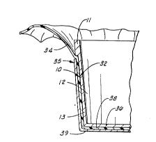
In Figure 5, the pot is again designated at 10 with the rim
11, pot portion 12 and bottom 13. In Figure 5 it will be seen
that there is an inner sleeve 32 covering the pot portion 12
of the flower pot 10. Next to the inner sleeve 32 is the
sheet of material designated at 34: and, to hold the sheet of
material 34 in place, there is an outer sleeve 35.
As shown in Figure 5, it will be seen that the
bottom 36 of the flower pot 10 is also covered by a bottom
, . , . . . . _ . .... _ . .. .. _ _ ... . . . . . .
20~
g .,
portion 38 of the inner sleeve 32. Thus, the entire pot
portion 12 of the flower pot 10 i8 covered by the inner sleeve
32 to prevent the passage of moisture from the pot 10 to the
fabric 24. 5imilarly, as here shown the sleeve 35 includes
5 a bottom portion 38. It will be obvious to those skilled in
the art that the bottom portion 39 can be omitted, but the
flower pot 10 would then be resting on the fabric 24. This
may n,~t be objectionable since the inner sleeve 32 includes
the bottom portion 38 to protect the fabric 24 from moisture.
In using the system shown in Figure 5 of the
drawi~lgs, it will be understood that the system will be
sub6tantially the same as that discussed above. The outer
sleeve 35 will have the sleeve material 34 placed thereover.
One will then place the flower pot 10 into the inner sleeve
32; and, the covered flower pot can then be set into the outer
sleeve 35, allowing the sheet of material 34 to be pleated as
nPc~R~ry to fill the space between the inner sleeve 32 and
the outer sleeve 35. It will further be understood that a
substantially circular piece of sheet of material such as the
material 14 can be utilized, or a heavier, notched piece of
sheet of material such as the sheet of material 14a can be
utilized in the arrangement in Figure 5 of the drawings.
It will therefore be seen that the present invention
provides a very quick and easy flower pot cover/wrap system
that can be used with inexpensive sheets of material can be
printed with various designs, or be a solid color, and can
even be transparent if such an effect is desired. Through the
use of the sleeve 15, installation of the sheet of material
such as the material 14 will be very quick, taking only a few
seconds for compete covering of the pot such as the flower pot
10. H'eavy sheets of material can be used by utilizing the
arrangement shown in Figure 4 of the drawings, and delicate
fabrics and the like can be utilized by using the inner sleeve
32 in conjunction with the outer sleeve 16 or 35.
~ Shown in Figure 6 is one system which may be used
for forming a flower pot cover using the segmented sheet of
material shown in Figure 4. As shown in Figure 6, the sheet
_ _ _ ..... .. .. _ _ _ _ _ _
206~0
of material 14a is positioned generally above a remale mold
40 ha~ing a mold opening 42 in a po6ition wherein the base 20
of the sheet of material 14a is positioned generally over the
female mold opening 42 and the segments 21 each extend
5 outwardly therefrom. A male mold 44 is connected to a
cylinder rod of a hydraulic cylinder 46. The male mold 44 is
shaped to be matingly disposed in the female mold 40.
In operation, the hydraulic cylinder 46 is actuated
to move the male die 44 in the downward direction 48 to a
10 position wherein the lower end of the male die engages the
base 20 of the sheet of material 14a. The male die 44 further
is moved in the downward direction pushing the base 20 and the
segents 21 connected thereto into the female mold 40. As the
sheet of material 14a is pushed into the femalc mold the
lS segments are formed in an upward direction extending generally
upwardly from the base 20. As mentioned before, the segments
21 are shaped so that, when the segments have been moved in
the upward direction and the male mold 44 is matingly ~;qposP~l
in the female mold 40, a portion of the side 28 of each of the
20 segments 21 overlap an adjacent portion of the side 26 of the
adjacent 6egment. The sides 28 and 26 of each of the segments
21 are connected to form the decorative cover 50 as shown in
Figure 7. The overlapping edges 26 and 28 may be sealingly
connected by heat sealing when the cover is formed from a heat
25 sealable material such as polypropylene for example. In other
instances, it may be n~cpqs~ry to connect the overlapping
sides 26 and 28 by adhesively connecting the overlapping
portion of the sides 26 and 28 of each of the segments 21.
Changes may be made in the construction of the
30 various part, elements, and assemblies described herein and
changes may be made in the steps or the sequence of steps of
the methods de6cribed herein without departing from the spirit
and scope of the invention as defined in the following claims.