Sélection de la langue

Search

Sommaire du brevet 2061438 

Énoncé de désistement de responsabilité concernant l'information provenant de tiers

Une partie des informations de ce site Web a été fournie par des sources externes. Le gouvernement du Canada n'assume aucune responsabilité concernant la précision, l'actualité ou la fiabilité des informations fournies par les sources externes. Les utilisateurs qui désirent employer cette information devraient consulter directement la source des informations. Le contenu fourni par les sources externes n'est pas assujetti aux exigences sur les langues officielles, la protection des renseignements personnels et l'accessibilité.

Disponibilité de l'Abrégé et des Revendications

L'apparition de différences dans le texte et l'image des Revendications et de l'Abrégé dépend du moment auquel le document est publié. Les textes des Revendications et de l'Abrégé sont affichés :

  • lorsque la demande peut être examinée par le public;
  • lorsque le brevet est émis (délivrance).
(12) Demande de brevet: (11) CA 2061438
(54) Titre français: CAPUCHON DE STYLO ET D'ARTICLES DU GENRE
(54) Titre anglais: CAP OF WRITING INSTRUMENT AND THE LIKE
Statut: Réputée abandonnée et au-delà du délai pour le rétablissement - en attente de la réponse à l’avis de communication rejetée
Données bibliographiques
Abrégés

Abrégé anglais


ABSTRACT
An improved cap of writing instruments comprises an
inner cap 18 inserted therein in axially movable manner. The
inner cap has a bottomed sealing member 23 made of an elastomer
closely inserted therein and an opening 8 formed at rear end
thereof. Plural ribs 13 are formed on the inside of a rear end
portion of the cap, while other plural ribs 19 are formed on
the outside of an front end portion of the inner cap so that
there may be formed a gaps 17, 22 between the cap and the inner
cap to provide an air passage through the interior of the cap.
There are formed first and second annular engaging protrusions
11, 12 on the inner surface of the cap, one for stopping the
inner cap and the other for engaging with an annular engaging
protrusion 4 provided on the front end of a writing shaft 3.

Revendications

Note : Les revendications sont présentées dans la langue officielle dans laquelle elles ont été soumises.


THE EMBODIMENTS OF THE INVENTION IN WHICH AN EXCLUSIVE
PROPERTY OR PRIVILEGE IS CLAIMED ARE DEFINED AS FOLLOWS:
In a cap of a sign pen, marker, aqueous ball pen or
the like to be put on the writing front end portion for
preventing ink from vaporizing, the improvement which
comprises:
plural ribs (13) formed at suitable places on rear
end side of an inner hole (10) of a cap (6);
an opening (8) formed on the rear end of the cap;
first and second annular engaging protrusions (11)
and (12) formed in side on a front end portion and a middle
portion;
a bottomed tubular inner cap (18) rear end closed
with a ceiling 21, in the front side of which is closely
inserted a bottomed tubular sealing member (23) airtightly
formed of an elastomer and on front side outer periphery of
which are formed ribs (19) at suitable places, said inner cap
being movably inserted in the inner hole (10);
a spring (24) loaded between the front end step
portion (16) of the ribs (13) and the rear end step portion
(20) of the ribs (19) so as to energize the front end of the
inner cap (18) to elastically engage with the engaging
protrusion (12) while preventing it from further moving toward
the inserting side of the writing body;
an air passage formed to communicate the inner hole
(10) from the front end of the inner cap (18) with open air;
the engaging protrusion (11) being such arranged
that, when the writing body (2) is inserted in the inner hole
(10) with an engaging portion (4) provided on a shaft (3)
- 7 -

caught by the engaging protrusion (11) of the cap, the front
portion of the shaft (3) is closely inserted in the sealing
member (23) and the inner cap (18) retreats while the front end
of the writing tip (5) compressing the rear end wall of the
sealing member (23) so that the ceiling portion (21) nearly
evens with the rear end outer surface (15) of the cap.
- 8 -

Description

Note : Les descriptions sont présentées dans la langue officielle dans laquelle elles ont été soumises.

~3~
CAP OF WRITING INSTRUMENT AND THE LIKE
BACKGROUND OF THE INVENTION
Field of the invention
The present invention relates to an improved cap put
on the front end of writing instruments such as a sign pen,
marker, aqueous ball pen and the like to prevent evaporation of
the ink contained therein.
Prior Art
Conventional caps used for a sign pen, marker and the
like are formed of resin materials excellent in ink evaporation
suppressibility, an~ are put on the front end of the writing
instrument, with the front end tightly inserted in an inner
hole of the cap or an inner cap provided on the inner hole.
With the conventional caps used for the sign pen,
marker and the like, it is possible such accident to occur
although very rarely depending upon the size and shape thereof
that, since the inner hole is in a blocked condition except for
the inserting side, any little child swallows the cap by
mistake which in turn clogs the throat thereby resulting in
asphyxiation.
SUMMARY OF THE INVENTION
An object of the present invention is to avoid the
risks of asphyxiation and the like in such circumference as
above by making the ventilation possible even if any little
child swallows the cap by mistake which in turn clogs the
throat and to prevent the hand or clothing of the user from
being stained by ink which spouts out from the writing tip and
an air hole provided about the writing tip (so-called pumping
.
. .
. . . .
.

2~
phenomenon), with the inner pressure within the cap reduced or
elevated when the cap is taken out or put thereon. The cap for
writing instruments according to the present invention
contrived in order to achieve the above object comprises an
inner cap with a sealing member made of an elastomer inserted
therein, a spring loaded to energize the inner cap to be
axially movable, plural ribs formed on one portion of the cap
and on other portion of the inner cap respectively to provide
suitable gaps therebetween, and a hole formed on the rear end
of the cap, said gaps and the rear end hole providing an air
passage communicating the inner hole of the cap with open air.
When a writing body is inserted in the cap, the front end of
the writing body is closely inserted in the sealing member with
the inner cap axially moved and thus there can be prevented the
getting dry of the writing tip and the evaporation of ink.
With the inner cap axially moved following the putting on or
taking out of the cap, any pressurization and depressurization
within the cap and sealing member can be prevented and thus
there can be prevented the hand or clothing of the user from
being stained by ink otherwise spouts out.
BRIEF DESCRIPTION OF THE DRAWINGS
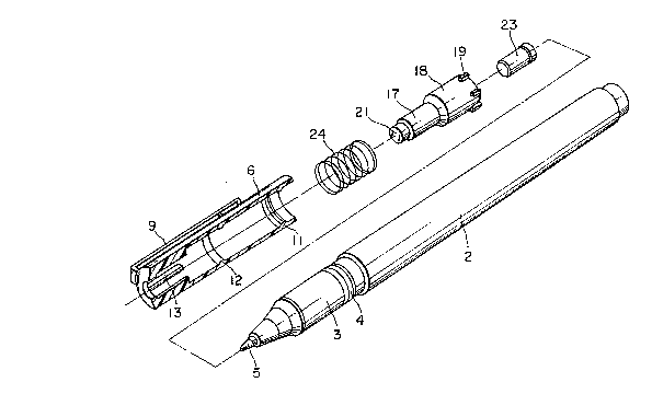
Fig. 1 is a perspective view of a writing instrument
to which an embodiment of the present invention is applied;
Fig. 2 is a perspective view showing a condition
where a cap is taken out of a writing body;
Fig. 3 is a perspective view showing the writing body
and the cap exploded and shown partly in vertical section;
Fig. 4 shows a half sectional view of the cap in a
- 2 -
.
.
'

condition where the writing body is completely inserted
thereinto;
Fig. 5 is a cross-section taken along line V - V in
Fig. 4;
Fig. 6 is a cross-section taken along line VI VI in
Fig. 4; and
Fig. 7 is a half cross-sectional view of the cap
portion in a condition directly before the writing body is
inserted thereinto.
DETAILED DESCRIPTION
Referring now to the accompanying drawings showing an
embodiment, the present invention will be described futher in
detail. The present invention is designed, in a cap of a sign
pen, marker, aqueous ball pen, etc., put on the writing front
tip thereof to prevent evaporation of ink therefrom, such that,
even if accidentally swallowed in by a little child, it does
not asphyxiate the child thanks to an air passage provided .
therein and fllrther that ink does not spout out from the
writing tip or an air hole thereabout under pressurization or
depressurization in the case of the insertion or removal of the
writing body in or from the cap to stain the hand or clothing
of a user. As shown in Figs. 3 - 7, plural ribs 13 are
provided at suitable places on the rear end side wall of an
inner hole 10 of a cap 6. Through the rear end wall with a
rear surface 15 of the cap 6, an opening 8 is formed leaving a
stepped portion 14. On the inner face of the cap 6 are formed
first and second annular engaging protrusions 11, 12. There is
housed in the cap a bottomed tubular inner cap 18 whose rear
~: :
- 3
. -
: :
,
~:
.: : . .~
~ .

2~
end is closed to form a ceiling portion 21~ The inner cap 18
has a front end hole in which a bottomed sealing member 23
airtightly formed of an elastomer is inserted and a plurality
of ribs 19 are formed at suitable places on the front end outer
periphery thereof. The inner cap 18 is inserted in the inner
hole 10 of the above cap with a compression spring 24 energing
between the front end step portions 16 of the above ribs and
the rear end step portions 20 of the ribs 19 so that the front
end of the inner cap 18 may be elastically engaged with the
engaging portion 12 provided on the inner hole 10 of the cap to
prevent the writing body 2 from moving toward the inserting
side while allowing the inner cap 18 to move rearward relative
to the cap 8. There are formed plural gaps 17 and 22
respectively between the outer periphery of the inner cap 18
and the ribs 13 of the inner hole 10 and between the inner hole
10 and the ribs 18 of the inner cap 18 to provide an air
passage between the rear end opening 8 of the cap and the inner
hole 10 for communicating with the open air.
While, at front portion on a shaft 3 of the writing
body 2 is formed an annular engaging protrusion 4 and on the
front end of the shaft 3 is provided a writing tip 5 of an
aqueous ball pen or the like. In the writing body 2 is
contained a liquid ink, while, between the interior therof an~
the writing tip is provided a control device (not shown) for
properly adjusting the outflow of ink and for reserving ink
depending on change of the inner pressure in the ink reservoir.
Location of the annular engaging protrusion 11 of the cap is
such arranged that, when it catches the annular engaging
- 4 -
.
' , . :

3~3
protrusion 4 of the shaft 3 with the writing body 2 inserted
into the inner hole 10 of the cap, the inner cap 18 retreats by
a distance S as shown in Fig. 4 with the front portion of the
shaft 3 pressing the rear end wall of the sealing member 23 and
at that time the ceiling 21 of the inner cap 18 virtually evens
with the rear end outer surface of the cap.
(Function)
The present invention is designed as above and, in a
condition where the writing body 2 is fully inserted in the cap
as shown in Fig 4, the front poriton of the writing body is
closely inserted in the sealing member 23 with the writing tip
5 pressed onto the rear end wall of the sealing member 23.
Accordingly, there can be prevented both the getting dry of the
writing tip and the evaporation of ink from the air hole
provided thereabout. Futher, since the insertion is carried
out with the inner cap 18 simultaneously retreating, the
interiors of the cap and the sealing member are not
pressuriged. While, when the writing body 2 is removed from
the cap 6, the inner cap 18 is returned inward by the returning
force of the spring 34 while following the writing body 2, and
thus there does not take place any depressurization.
Accordingly, no ink spouts out from the writing tip and the air
hole. Further, since an air passage is formed which
communicates the inner hole 10 with the opening 8 in the
condition where the writing body 2 is removed from the cap 6,
there can be prevented accidents such as asphyxiation and the
like even if the cap is swallowed by mistake to clog the
throat.
- 5 -
' ~ '
~, .: , .

Z~
(Effect of the invention)
Since the construciton and the function of the
present invention is described above, even i~ any little child
swallows the cap by mistake to clog the throat, there can be
avoided accidents such as aasphyxiation and the like, with open
air allowed to pass the interior of the cap which has an air
passage provided between the rear end opening and the cap's
inner hole. Further, the above construction provides no
inferiority in apprearence. Moreover, since there is not
caused any pressurization or depressurization in the interior
of the cap and the front portion of the writing body, there can
be prevented such problem that ink sports out from the writing
tip or the air hole to stain the hand and the clothing of the
user.
.
.
- 6 - ~
.
,
,

Dessin représentatif
Une figure unique qui représente un dessin illustrant l'invention.
États administratifs

2024-08-01 : Dans le cadre de la transition vers les Brevets de nouvelle génération (BNG), la base de données sur les brevets canadiens (BDBC) contient désormais un Historique d'événement plus détaillé, qui reproduit le Journal des événements de notre nouvelle solution interne.

Veuillez noter que les événements débutant par « Inactive : » se réfèrent à des événements qui ne sont plus utilisés dans notre nouvelle solution interne.

Pour une meilleure compréhension de l'état de la demande ou brevet qui figure sur cette page, la rubrique Mise en garde , et les descriptions de Brevet , Historique d'événement , Taxes périodiques et Historique des paiements devraient être consultées.

Historique d'événement

Description Date
Inactive : CIB désactivée 2016-01-16
Inactive : CIB attribuée 2015-08-20
Inactive : CIB en 1re position 2015-08-20
Demande non rétablie avant l'échéance 2000-02-18
Le délai pour l'annulation est expiré 2000-02-18
Inactive : Abandon.-RE+surtaxe impayées-Corr envoyée 1999-02-18
Réputée abandonnée - omission de répondre à un avis sur les taxes pour le maintien en état 1999-02-18
Demande publiée (accessible au public) 1993-08-19

Historique d'abandonnement

Date d'abandonnement Raison Date de rétablissement
1999-02-18

Taxes périodiques

Le dernier paiement a été reçu le 1998-01-30

Avis : Si le paiement en totalité n'a pas été reçu au plus tard à la date indiquée, une taxe supplémentaire peut être imposée, soit une des taxes suivantes :

  • taxe de rétablissement ;
  • taxe pour paiement en souffrance ; ou
  • taxe additionnelle pour le renversement d'une péremption réputée.

Les taxes sur les brevets sont ajustées au 1er janvier de chaque année. Les montants ci-dessus sont les montants actuels s'ils sont reçus au plus tard le 31 décembre de l'année en cours.
Veuillez vous référer à la page web des taxes sur les brevets de l'OPIC pour voir tous les montants actuels des taxes.

Historique des taxes

Type de taxes Anniversaire Échéance Date payée
TM (demande, 6e anniv.) - générale 06 1998-02-18 1998-01-30
Titulaires au dossier

Les titulaires actuels et antérieures au dossier sont affichés en ordre alphabétique.

Titulaires actuels au dossier
MITSUBISHI PENCIL CO., LTD.
Titulaires antérieures au dossier
TAKASHI ISODA
Les propriétaires antérieurs qui ne figurent pas dans la liste des « Propriétaires au dossier » apparaîtront dans d'autres documents au dossier.
Documents

Pour visionner les fichiers sélectionnés, entrer le code reCAPTCHA :


Pour visualiser une image, cliquer sur un lien dans la colonne description du document. Pour télécharger l'image (les images), cliquer l'une ou plusieurs cases à cocher dans la première colonne et ensuite cliquer sur le bouton "Télécharger sélection en format PDF (archive Zip)" ou le bouton "Télécharger sélection (en un fichier PDF fusionné)".

Liste des documents de brevet publiés et non publiés sur la BDBC .

Si vous avez des difficultés à accéder au contenu, veuillez communiquer avec le Centre de services à la clientèle au 1-866-997-1936, ou envoyer un courriel au Centre de service à la clientèle de l'OPIC.


Description du
Document 
Date
(aaaa-mm-jj) 
Nombre de pages   Taille de l'image (Ko) 
Revendications 1993-08-18 2 47
Dessins 1993-08-18 3 95
Abrégé 1993-08-18 1 25
Description 1993-08-18 6 204
Dessin représentatif 1998-08-31 1 19
Rappel - requête d'examen 1998-10-19 1 116
Courtoisie - Lettre d'abandon (taxe de maintien en état) 1999-03-17 1 187
Courtoisie - Lettre d'abandon (requête d'examen) 1999-03-31 1 172
Taxes 1997-01-16 1 63
Taxes 1996-02-15 1 57
Taxes 1995-02-13 1 75
Taxes 1994-01-26 1 46