Sélection de la langue

Search

Sommaire du brevet 2061747 

Énoncé de désistement de responsabilité concernant l'information provenant de tiers

Une partie des informations de ce site Web a été fournie par des sources externes. Le gouvernement du Canada n'assume aucune responsabilité concernant la précision, l'actualité ou la fiabilité des informations fournies par les sources externes. Les utilisateurs qui désirent employer cette information devraient consulter directement la source des informations. Le contenu fourni par les sources externes n'est pas assujetti aux exigences sur les langues officielles, la protection des renseignements personnels et l'accessibilité.

Disponibilité de l'Abrégé et des Revendications

L'apparition de différences dans le texte et l'image des Revendications et de l'Abrégé dépend du moment auquel le document est publié. Les textes des Revendications et de l'Abrégé sont affichés :

  • lorsque la demande peut être examinée par le public;
  • lorsque le brevet est émis (délivrance).
(12) Brevet: (11) CA 2061747
(54) Titre français: PANNEAU DE FENETRE AVEC PRISE D'AIR
(54) Titre anglais: WINDOW PANEL WITH BREATHER SYSTEM
Statut: Périmé et au-delà du délai pour l’annulation
Données bibliographiques
(51) Classification internationale des brevets (CIB):
  • E06B 7/02 (2006.01)
  • E06B 3/677 (2006.01)
  • E06B 7/12 (2006.01)
(72) Inventeurs :
  • BAIER, BRUCE A. (Etats-Unis d'Amérique)
  • HAGEMEYER, BRUCE A. (Etats-Unis d'Amérique)
  • ROLFFS, MERLAN J. (Etats-Unis d'Amérique)
  • SCHARFF, JOHN W. (Etats-Unis d'Amérique)
(73) Titulaires :
  • PELLA CORPORATION
(71) Demandeurs :
  • PELLA CORPORATION (Etats-Unis d'Amérique)
(74) Agent: SMART & BIGGAR LP
(74) Co-agent:
(45) Délivré: 1996-06-25
(22) Date de dépôt: 1992-02-24
(41) Mise à la disponibilité du public: 1993-05-19
Requête d'examen: 1992-02-24
Licence disponible: S.O.
Cédé au domaine public: S.O.
(25) Langue des documents déposés: Anglais

Traité de coopération en matière de brevets (PCT): Non

(30) Données de priorité de la demande:
Numéro de la demande Pays / territoire Date
07/793,475 (Etats-Unis d'Amérique) 1991-11-18

Abrégés

Abrégé anglais


A dual glazing window having a removable glazing
panel 32 is provided with a breather system
connecting the air chamber 34 between the glazing
panels 30 and 32 with the outside ambient air by
routing an outwardly facing channel 38 into the
window rail 26 or stile member 60 either on its end
edge or side face. The abutting rail or stile member
will close the open side of the channel in the end
edge while the adjacent glazing panel closes the
channel in the side face. A breather sleeve 68 is
press fitted into the channel to protect the wood
from absorbing moisture.

Revendications

Note : Les revendications sont présentées dans la langue officielle dans laquelle elles ont été soumises.


The embodiments of the invention in which an
exclusive property or privilege is claimed are defined
as follows:
1.
A window panel comprising:
a perimeter frame having oppositely disposed stile
frame members and oppositely disposed rail
frame members defining a glazing opening;
a pair of spaced apart glazing panels having an air
chamber therebetween positioned in said glazing
opening; and
at least one of said rail members having a face in
abutting engagement with one of said stile
members, said face having a channel formed in
it extending from said air chamber to the
exterior of said perimeter frame whereby said
air chamber is in communication with outside
ambient air.
2.
The structure of claim 1 wherein said channel
includes a breather sleeve extending the length of
said channel.
3.
The structure of claim 1 wherein said face is
further defined as being in an end edge of said one
rail member.
4.
The structure of claim 3 wherein said one stile
member has oppositely facing interior and exterior
faces and said face having said channel engages said
interior face of said stile member.
5.
The structure of claim 4 wherein said channel
is U-shaped and open on one side and said interior
face of said one stile member closes said open one
side of said channel.

6.
The structure of claim 5 wherein said closed
channel includes a breather sleeve extending the
substantial length thereof.
7.
The structure of claim 3 wherein said one stile
member has oppositely facing interior and exterior
faces and said face having said channel engages said
interior face of said one stile member.
8.
The structure of claim 7 wherein said channel
is U-shaped and open on one side and said interior
face of said one stile member closes said open one
side of said channel.
9.
The structure of claim 8 wherein said closed
channel includes a breather sleeve extending the
substantial length thereof.
10.
A window panel comprising:
a perimeter frame having oppositely disposed stile
frame members and oppositely disposed rail
frame members defining a glazing opening;
a pair of spaced apart glazing panels having an air
chamber therebetween positioned in said glazing
opening; and
at least one of said stile members having a face in
abutting engagement with one of said rail
members, said face having a channel formed in
it extending from said air chamber to the
exterior of said perimeter frame whereby said
air chamber is in communication with outside
ambient air.

11.
The structure of claim 10 wherein said channel
includes a breather sleeve extending the length of
said channel.
12.
The structure of claim 10 wherein said face is
further defined as being in an end edge of said one
stile member.
13.
A window panel comprising:
a perimeter frame having oppositely disposed stile
frame members and oppositely disposed rail
frame members defining a glazing opening;
a pair of spaced apart glazing panels having an air
chamber therebetween positioned in said glazing
opening; and
at least one of said rail members having a face in
abutting engagement with one of said glazing
panels, said face having a channel formed in it
extending from said air chamber to the exterior
of said perimeter frame whereby said air
chamber is in communication with outside
ambient air.
14.
The structure of claim 13 wherein said channel
includes a breather sleeve extending the length of
said channel.
15.
The structure of claim 13 wherein said channel
is U-shaped and open on one side and said one
glazing panel closes said open one side of said
channel.

16.
The structure of claim 13 wherein said face
having said channel is further defined by said
channel being U-shaped and open on one side and said
one of said glazing panels closes said open one side
of said channel.
17.
The structure of claim 16 wherein said closed
channel includes a breather sleeve extending the
substantial length thereof.
18.
The structure of claim 17 wherein said breather
sleeve is L-shaped and includes one leg extending
the length of said channel and a second leg
extending outwardly from said face closely adjacent
an outer peripheral edge of said one glazing panel
and into a plane containing said one glazing panel.
19.
The structure of claim 13 wherein said one
glazing panel closes an open side of said channel to
define a passageway for providing said communication
between said air chamber and the outside ambient
air.
20.
The structure of claim 19 wherein aerated metal
facing and retaining means are positioned on and in
engagement with the side of said one glazing panel
opposite said channel in said face thereby obscuring
the presence of said channel and connecting said one
glazing panel to said one rail member.

11
21.
A window panel comprising:
a perimeter frame having oppositely disposed stile
frame members and oppositely disposed rail
frame members defining a glazing opening;
a pair of spaced apart glazing panels having an air
chamber therebetween positioned in said glazing
opening, and
at least one of said stile members having a face in
abutting engagement with one of said glazing
panels, said face having a channel formed in it
extending from said air chamber to the exterior
of said perimeter frame whereby said air
chamber is in communication with outside
ambient air.
22.
The structure of claim 21 wherein said channel
includes a breather sleeve extending the length of
said channel.
23.
The structure of claim 21 wherein said channel
is U-shaped and open on one side and said one
glazing panel closes said open one side of said
channel.
24.
The structure of claim 21 wherein said face
having said channel is further defined by said
channel being U-shaped and open on one side and said
one of said glazing panels closes said open one side
of said channel.
25.
The structure of claim 24 wherein said closed
channel includes a breather sleeve extending the
substantial length thereof.

12
26.
The structure of claim 25 wherein said breather
sleeve is L-shaped and includes one leg extending
the length of said channel and a second leg
extending outwardly from said face closely adjacent
an outer peripheral edge of said one glazing panel
and into a plane containing said one glazing panel.
27.
The structure of claim 21 wherein said one
glazing panel closes an open side of said channel to
define a passageway for providing said communication
between said air chamber and the outside ambient
air.
28.
The structure of claim 27 wherein aerated metal
facing and retaining means are positioned on and in
engagement with the side of said one glazing panel
opposite said channel in said face thereby obscuring
the presence of said channel and connecting said one
glazing panel to said one stile member.

Description

Note : Les descriptions sont présentées dans la langue officielle dans laquelle elles ont été soumises.

206 ~ 7~7
BACKGROUND OF THE INVENTION
Many windows are manufactured for high energy
efficiency by utilizing dual glazing panels with an
insulating air space therebetween. Typically, the
interior glazing panel is removable. Such a design
requires that the insulating air space be vented to
the atmosphere to prevent excessive moisture build
up which results in condensation on the glazing
panels. Such ventilation is usually provided by
drilling holes through the sash frame. An example
of this is shown in the U.S. patent 4,627,206 dated
Dec. 19, 1986. A pair of drilled interconnecting
holes are illustrated in this patent.
A breather system is needed that involves a
minimum number of manufacturing steps but is
effective in venting the insulating air space.
SUMMARY OF THE INVENTION
The insulating air space between dual glazing
panels is vented to the external ambient air through
a channel produced by a single routing step in the
manufacture of the window panel. The channel is
routed into a face of the rail or stile members
comprising the perimeter frame. The open channel is
closed in one embodiment by engagement with one of
the glazing panels. In an alternate embodiment the
" ~,

206 1~97
channel is formed in the end face of the stile or
rail member and is closed by abutting engagement with
the adjacent stile or rail member.
A breather sleeve may be inserted into the
channel formed in the face of the stile or rail
window frame members to protect the wood in the
channel from absorbing moisture. In the case of the
channel closed by the glazing panel, the sleeve is L-
shaped and extends along the length of the channel
and then outwardly along the peripheral edge of the
glazing panel. The channel in this case is formed in
the side face of the glazing stop portion of the rail
or stile member.
DESCRIPTION OF THE DRAWINGS
Figure l is a fragmentary perspective view of a
wall having a window assembly which includes the
breather system of this invention.
Figure 2 is a cross sectional view taken along
line 2 - 2 in Figure l.
Figure 3 is an enlarged cross sectional view
taken along line 3 - 3 in Figure 2.
Figure 4 is a cross sectional view taken along
line 4 - 4 in Figure 2.
Figure 5 is a perspective view of an L-shaped
breather sleeve.

~ 3 ~ 206 1 747
Figure 6 is a cross sectional view of a prior
art breather system in a window panel.
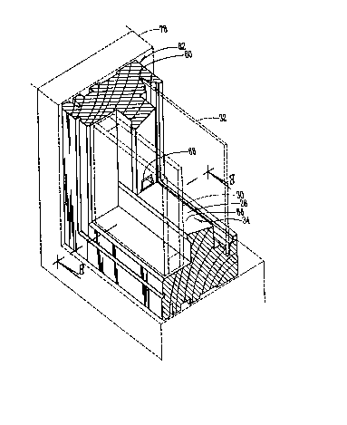
Figure 7 is a fragmentary perspective view of a
breather system in a window panel of an alternate
construction wherein the channel is in the end edge
of a stile or rail window frame member.
Figure 8 is a cross sectional view taken along
line 8 - 8 in Figure 7.
Figure 9 is a view similar to Figure 8 but
showing only the profile of the stile member having
the channel routed into it.
Figure 10 is a cross sectional view taken along
line 10 - 10 in Figure 8.
Figure 11 is a perspective view of a breather
sleeve.
Figure 12 is a perspective view of the breather
sleeve of Figure 11 showing it from its opposite
end.
Figure 13 is a cross sectional view taken along
line 13 - 13 in Figure 12.
Figure 14 is a view similar to Figure 7 but
showing the channel in the end edge of the rail
window frame member.
Figure 15 is a cross sectional view taken along
line 15 - 15 in Figure 1.
DESCRIPTION OF PREFERRED EMBODIMENT
A window assembly utilizing the breather system
of this invention is referred to in Figure 1
~'

` -
206 1 747
- 3A -
generally by the reference numeral 10 and is shown
mounted in a wall 12. The window assembly 10
includes individual window panels 14, 16 and 18
,, ~
~ ~,.,

206i~7
. ~
-- 4 --
mounted in a window opening frame which includes
oppositely disposed stile frame members 20 and rail
sill member 22 and rail head member 24.
The window panel 14 is seen to include a bottom
rail 26 having a glass stop 28 engaging an outer dual
insulated glass glazing panel 30. The glazing panel
30 with a removable glazing panel 32 define an
insulating air chamber 34 therebetween. The
removable panel 32 engages the rail stop portion 28
on the opposite side from glazing panel 30. Metal
cladding which functions as a glazing retainer 36
engages the outer face of the glazing panel 30.
The rail stop 28 has a U-shaped channel 38
formed in the face engaging the glazing panel 30. An
L-shaped breather sleeve 40 as seen in Figure 5 is
press fitted into the U-shaped channel 38.
The breather sleeve 40 includes a leg portion 42
which extends parallel to the glazing panel 30 and a
leg portion 44 which extends transversely thereof
along the adjacent peripheral edge of the glazing
panel 30 into the plane of the glazing panel. A
passageway 46 extends through the sleeve 40 to
provide communication between the air chamber 34 and
the outside ambient air through the metal cladding
and glazing retainer 36 as seen in Figure 2.

2 ~
-- 5 --
The breather sleeve 40 includes an outer flange
48 which limits insertion of the sleeve into the U-
shaped channel 38. Outwardly extending V-shaped
anchors 50 are provided on opposite side edges of
the sleeve 40 to lock the sleeve in the U-shaped
channel 38 when the sleeve is pressed into the
channel. The breather sleeve 40 assures that
moisture does not penetrate the wood in the glass
stop 28. The metal classing and glazing retainer 36
assures that dirt and insects do not enter the air
chamber 34 through the air passageway 46 of the
sleeve 40. The passageway 46 is very narrow further
restricting entry of insects.
An alternate window arrangement is illustrated
in Figures 7-13. A stile member 60 forming one side
of a window mainframe 62 includes a downwardly
facing routed channel 64 as seen in Figure 9. The
open side of the channel is closed by the adjacent
upwardly facing face 66 on the rail 28 as seen in
Figure 7. A breather sleeve 68 is press fitted into
the channel 64 to provide communication between the
insulating air space and the outside ambient air.
In Figure 14 the breather sleeve 68A is
positioned in a channel 64A in the end edge of the
rail 28 window frame member. The open end of the
channel 64A is closed by the interior face of the
adjacent stile member.
~3

- 5A -
In Figure 15 the breather sleeve 40A is
positioned in a channel 38A in the face of stile
member 60. It is seen that this embodiment is
similar to that of Figure 2, but the channel is in
the stile member rather than the rail. In each case
the channel is in the face which engages the glazing
panel 30.
The breather sleeve 68 is elongated with a stop
flange 70 on its outer end and insect restricting
fingers 72 extending across a passageway 74 therein.
Anchors 76 are provided on opposite sides to lock the

20S1747
breather sleeve 68 in the channel 64. It is seen
that the outer end of the breather sleeve 68 opens
into a space between the window wall frame 78 and the
stile 60. This space is in turn in communication
with the outside ambient air.
In operation it is seen that each window may
have a breather system that includes a breather
sleeve in each corner. The simplified but effective
system of this invention is essentially the result of
one manufacturing step, routing a channel into stile
and/or rail members of the window frame. Abutting
stile or rail members or the adjacent glazing panel
close the open side of the channel to form a
passageway from the interior air chamber to the
outside ambient air. Protection against moisture
deterioration of the wood is provided through use of
plastic sleeves that are press fitted into the
channels. Thus it is seen that the need for boring
several intersecting holes to form passageways has
been eliminated and the alignment problems have been
avoided. The appearance of the window is enhanced by
the obscure but effective breather system of this
invention.

Dessin représentatif
Une figure unique qui représente un dessin illustrant l'invention.
États administratifs

2024-08-01 : Dans le cadre de la transition vers les Brevets de nouvelle génération (BNG), la base de données sur les brevets canadiens (BDBC) contient désormais un Historique d'événement plus détaillé, qui reproduit le Journal des événements de notre nouvelle solution interne.

Veuillez noter que les événements débutant par « Inactive : » se réfèrent à des événements qui ne sont plus utilisés dans notre nouvelle solution interne.

Pour une meilleure compréhension de l'état de la demande ou brevet qui figure sur cette page, la rubrique Mise en garde , et les descriptions de Brevet , Historique d'événement , Taxes périodiques et Historique des paiements devraient être consultées.

Historique d'événement

Description Date
Inactive : CIB de MCD 2006-03-11
Le délai pour l'annulation est expiré 2005-02-24
Lettre envoyée 2004-02-24
Inactive : TME en retard traitée 2001-05-18
Lettre envoyée 2001-02-26
Accordé par délivrance 1996-06-25
Demande publiée (accessible au public) 1993-05-19
Toutes les exigences pour l'examen - jugée conforme 1992-02-24
Exigences pour une requête d'examen - jugée conforme 1992-02-24

Historique d'abandonnement

Il n'y a pas d'historique d'abandonnement

Historique des taxes

Type de taxes Anniversaire Échéance Date payée
TM (brevet, 6e anniv.) - générale 1998-02-24 1998-02-04
TM (brevet, 7e anniv.) - générale 1999-02-24 1999-02-10
TM (brevet, 8e anniv.) - générale 2000-02-24 2000-02-02
TM (brevet, 9e anniv.) - générale 2001-02-26 2001-05-18
Annulation de la péremption réputée 2001-02-26 2001-05-18
TM (brevet, 10e anniv.) - générale 2002-02-25 2002-02-12
TM (brevet, 11e anniv.) - générale 2003-02-24 2003-01-17
Titulaires au dossier

Les titulaires actuels et antérieures au dossier sont affichés en ordre alphabétique.

Titulaires actuels au dossier
PELLA CORPORATION
Titulaires antérieures au dossier
BRUCE A. BAIER
BRUCE A. HAGEMEYER
JOHN W. SCHARFF
MERLAN J. ROLFFS
Les propriétaires antérieurs qui ne figurent pas dans la liste des « Propriétaires au dossier » apparaîtront dans d'autres documents au dossier.
Documents

Pour visionner les fichiers sélectionnés, entrer le code reCAPTCHA :


Pour visualiser une image, cliquer sur un lien dans la colonne description du document. Pour télécharger l'image (les images), cliquer l'une ou plusieurs cases à cocher dans la première colonne et ensuite cliquer sur le bouton "Télécharger sélection en format PDF (archive Zip)" ou le bouton "Télécharger sélection (en un fichier PDF fusionné)".

Liste des documents de brevet publiés et non publiés sur la BDBC .

Si vous avez des difficultés à accéder au contenu, veuillez communiquer avec le Centre de services à la clientèle au 1-866-997-1936, ou envoyer un courriel au Centre de service à la clientèle de l'OPIC.


Description du
Document 
Date
(aaaa-mm-jj) 
Nombre de pages   Taille de l'image (Ko) 
Abrégé 1994-03-30 1 14
Page couverture 1994-03-30 1 13
Revendications 1994-03-30 3 65
Dessins 1994-03-30 2 95
Description 1994-03-30 6 151
Page couverture 1996-06-25 1 14
Description 1996-06-25 8 208
Abrégé 1996-06-25 1 17
Revendications 1996-06-25 6 181
Dessins 1996-06-25 3 143
Dessin représentatif 1998-10-29 1 19
Avis concernant la taxe de maintien 2001-03-26 1 178
Quittance d'un paiement en retard 2001-05-30 1 171
Avis concernant la taxe de maintien 2004-04-20 1 173
Taxes 2003-01-17 1 31
Taxes 2002-02-12 1 43
Taxes 1997-02-05 1 29
Taxes 1996-02-09 1 31
Taxes 1995-02-01 1 32
Taxes 1994-02-09 1 29
Correspondance de la poursuite 1993-06-15 1 25
Correspondance de la poursuite 1995-01-16 2 54
Correspondance de la poursuite 1995-09-08 2 58
Correspondance reliée au PCT 1996-04-17 1 35
Demande de l'examinateur 1994-07-15 2 75
Demande de l'examinateur 1995-03-09 1 53
Courtoisie - Lettre du bureau 1992-10-15 1 40