Une partie des informations de ce site Web a été fournie par des sources externes. Le gouvernement du Canada n'assume aucune responsabilité concernant la précision, l'actualité ou la fiabilité des informations fournies par les sources externes. Les utilisateurs qui désirent employer cette information devraient consulter directement la source des informations. Le contenu fourni par les sources externes n'est pas assujetti aux exigences sur les langues officielles, la protection des renseignements personnels et l'accessibilité.
L'apparition de différences dans le texte et l'image des Revendications et de l'Abrégé dépend du moment auquel le document est publié. Les textes des Revendications et de l'Abrégé sont affichés :
| (12) Brevet: | (11) CA 2062543 |
|---|---|
| (54) Titre français: | DISPOSITIF DE CONTROLE DU COMPORTEMENT D'UN BOULON D'ANCRAGE DE CABLE |
| (54) Titre anglais: | CABLE BOLT MONITORING DEVICE |
| Statut: | Réputé périmé |
| (51) Classification internationale des brevets (CIB): |
|
|---|---|
| (72) Inventeurs : |
|
| (73) Titulaires : |
|
| (71) Demandeurs : | |
| (74) Agent: | NADEAU, FRANCOIS |
| (74) Co-agent: | |
| (45) Délivré: | 1996-09-17 |
| (22) Date de dépôt: | 1992-03-09 |
| (41) Mise à la disponibilité du public: | 1993-09-10 |
| Requête d'examen: | 1993-02-05 |
| Licence disponible: | S.O. |
| (25) Langue des documents déposés: | Anglais |
| Traité de coopération en matière de brevets (PCT): | Non |
|---|
| (30) Données de priorité de la demande: | S.O. |
|---|
9
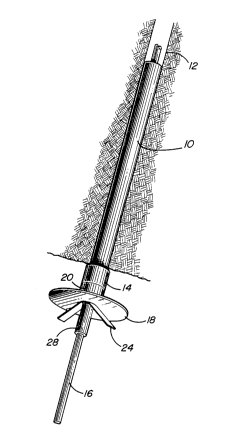
A monitoring unit for installation on a cable
bolt comprises a tube designed to fit within a cable bolt
hole and having a collar at one end thereof, a cable bolt
adapted to be grouted in the rock at the centre of the
tube, a base plate placed tightly against the tube collar
adjacent the rock face, a centralizer sleeve designed to
fit over the cable bolt to keep the cable centralized
within the base plate and tube, an elongated measuring
plate having a centre hole for insertion of the cable bolt
to fit tightly against the base plate and a groove cut at
equal distances from each side of the centre hole for
allowing the measuring plate to bend if the rock moves
with respect to the cable bolt, and a cable clamp for
fixing the measuring plate tight against the base plate.
Note : Les revendications sont présentées dans la langue officielle dans laquelle elles ont été soumises.
Note : Les descriptions sont présentées dans la langue officielle dans laquelle elles ont été soumises.
Pour une meilleure compréhension de l'état de la demande ou brevet qui figure sur cette page, la rubrique Mise en garde , et les descriptions de Brevet , États administratifs , Taxes périodiques et Historique des paiements devraient être consultées.
| Titre | Date |
|---|---|
| Date de délivrance prévu | 1996-09-17 |
| (22) Dépôt | 1992-03-09 |
| Requête d'examen | 1993-02-05 |
| (41) Mise à la disponibilité du public | 1993-09-10 |
| (45) Délivré | 1996-09-17 |
| Réputé périmé | 1999-03-09 |
Il n'y a pas d'historique d'abandonnement
| Type de taxes | Anniversaire | Échéance | Montant payé | Date payée |
|---|---|---|---|---|
| Le dépôt d'une demande de brevet | 0,00 $ | 1992-03-09 | ||
| Enregistrement de documents | 0,00 $ | 1993-03-12 | ||
| Taxe de maintien en état - Demande - nouvelle loi | 2 | 1994-03-09 | 100,00 $ | 1994-01-11 |
| Taxe de maintien en état - Demande - nouvelle loi | 3 | 1995-03-09 | 100,00 $ | 1994-12-09 |
| Taxe de maintien en état - Demande - nouvelle loi | 4 | 1996-03-11 | 100,00 $ | 1996-02-15 |
| Taxe de maintien en état - brevet - nouvelle loi | 5 | 1997-03-10 | 150,00 $ | 1997-02-17 |
Les titulaires actuels et antérieures au dossier sont affichés en ordre alphabétique.
| Titulaires actuels au dossier |
|---|
| NORANDA INC. |
| Titulaires antérieures au dossier |
|---|
| GENDRON, ALAIN |
| MILNE, DOUGLAS |
| POTVIN, YVES |

