Note : Les descriptions sont présentées dans la langue officielle dans laquelle elles ont été soumises.
2~6~
-- 1 --
TIRE INNER STITCHINC: MOLD
The present invention relates to a tire inner stitching
mold.
Co-pending Italian Patent Application n~T09lA000211,
filed concurrently by the present Applicant and to which
full reference is made herein in the interest of full
disclosure, relates to a method and device for joining
stratified tire portions by means of an inner stitching
operation, during which, the inner carcass of a green
tire and the outer tread belt are assembled together in-
side a fixed stitching mold by rotating stitching devic-
es over the inner surface of the carcass. The stitching
d~vices push the carcass outwards so as to adhere per-
~ectly to the tread belt, which in turn is pushed
against the inner surface of the mold in contact with
which the finished green tire is accurately formed~
It is an object of the present invention to provide a
tire inner stitching mold which, with relatively
low-cost modifications, may also be employed on existing
tire building machines.
2 ~ l g
-- 2 --
According to the present invention, there is provided a
tire inner stitching mold, characterised by the fact
that it comprises an annular gripping body for receiving
and retaining an outer tread belt; and two annular
shoulders located on opposite sides of said annular
gripping body and defining, with the same, a concave
annular stitching surface negatively matching the outer
shoulder and tread surface of a finished smooth-tread
tire; at least one of said two annular shoulders being
movable in relation to said annular gripping body.
Said annular gripping body and said annular shoulders
preferably constitute an inner portion of a grab ring
for transferring said outer tread belt to a carcass
building drum and removing from said drum a finished
green tire.
A number of non-limiting embodiments of the present in-
vention will be described by way of example with refer-
ence to the accompanying drawings, in which:
Fig.l shows a schematic axial cross section of a tire
building unit featuring a stitching mold in accordance
with the teachings of the present invention;
Fi~.2 shows a side view of a first preferred embodiment
of a tire grab ring incorporating the Fig.1 stitching
mold;
Fig.3 shows a larger-scale section along line III-III in
Fig.2;
Fig.4 shows an axial section, similar to Fig.3, of a
second preferred embodiment of the Fig.1 stitching mold.
2 ~
-- 3 --
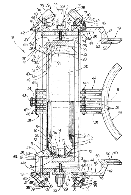
Number 1 in Fig.l indicates a unit for building a green
tire 2 comprising a tread belt 3 and an inner carcass 4
with two metal beads 5, and having an outer tread and
shoulder surface 2a.
Unit 1 comprises a tire building device consisting of a
building drum 6 extsnding through tire 2 and in turn
comprising a hollow, powered inner shaft 7 rotating
about an axis 8 coincident with the axis of tire 2; and
a stitching mold 9 open along its inner surface and lo-
cated outside drum 6 and coaxial with axis 8.
Drum 6 is defined by two coaxial half drums 10 and 11
facing respective bead portions 12 of tire 2 and defin-
ing an annular opening 13 located centrally, in use, be-
tween bead portions 12 of tire 2 housed inside mold 9.
A detailed description of building drum 6 is provided in
co-pending Italian Patent Application n.T09lA00~212
filed concurrently by the present Applicant and to which
full reference is made herein in the interest of ~ull
disclosure.
Unit 1 also comprises an inner stitching device 14 form-
ing a portion of drum 6, supported on an intermediate
poxtion o~ shaft 7, and comprising a number of stitching
elements 15 (only two of which are shown in Fig.1) mov-
ing radially, in relation to shaft 7, between a with-
drawn idle position wherein elements 15 are located in-
side drum 6, and an extracted operating position wherein
elements 15 engage the inner surface 2b of carcass 4 of
tire 2.
- ~ - 2~6 4119
Stitching device 14 is the object of said Italian Patent
Application n.T09lA000211.
As shown in Fig.2, stitching mold 9 forms an inner por-
tion of a grab ring 16 comprising an outer annular body
17, and an inner annular body 18 coaxial with outer
annular body 17 and defined by a number of sectors 20.
For each sector 20, ring 16 also comprises a connecting
and guide device 21 connected to sector 20 for connect-
in~ it to outer annular body 17 and guiding it, in rela-
tion to outer annular body 17, along a radial path as it
is moved, by a linear pneumatic actuator 22 on outer
annular body 17, between an outer idle position (not
shown) wherein the facing ends of each pair of adjacent
sectors 20 are parted, and an inner grab position where-
in said facing ends are arranged substantially contact-
ing each other.
As shown in Fig.2, each device 21 comprises a plate 23
connected integral with a central portion of the outer
surface 24 (Fig.3) of respective sector 20; and two rods
~5 integral with and extending substantially radially
outwards from plate 23, and engaging in sliding manner a
respective through slot 26 formed radially through outer
annular body 17 and closed by a plate 27. Plate 27 is
fitted through with rods 25, and supports a friction
guide element 28 for and engaged in sliding manner by
each rod 25. Plate 27 also supports the body 29 of actu-
ator 22, the output rod 30 of which extends radially
- 5 - 2~ 9
inwards through plate ~7 and is connected by its free
end to the outer surface of plate 23.
As shown in Fig.3, each sector ~o presents an inner sur-
face 31 comprising two end portions 32 in the form of a
flat cylindrical sector; and an intermediate portion 33
having a concave cross section with its concave side
facing inwards. In particular, the shape of intermediate
portion 33 negatively matches that assumed by the outer
sllrface of tread belt 3 of a finished smooth-tread tire
of the same size as grab ring 16.
~rab ring 16 also comprises two rings 34, each fitted in
removable manner on to a respective end of outer annular
body 17 and releasably connected to the same by means of
a respective bayonet joint 35.
By means of respective pins 36 perpendicular to axis 8
and substantially tangent to the outer surface of ring
34, each ring 34 is fitted with a number of equ-
ally-spaced levers 37, each having a fixed angular posi-
tion about the axis of respective pin 36. Each lever 37
is inclined outwards in relation to respective ring 34,
and is fitted integrally on its free end with the body
3~ o~ a pn~umatic actuator 39 perpendicular to lever 37
and having an output rod 40 located axially outside re-
spective ring 34 and facing axis 8. The end portion of
rod 40 consists of a fork 41 pivoting at 42 on the free
end of a first arm 43 of a square rocker arm 44, the
second arm 45 of which, perpendicular to arm 44,
2 ~
-- 6 --
consists of a number of parallel rods 46, each having an
end portion 47 bent square and parallel to arm 43.
At 44a, where arms 43 and 45 join, each rocker arm 44
pivots on the end of a respective appendix 48 extending
axially outwards from respective ring 34 at the connect-
ing point of respective lever 37, so as to rotate in re-
lation to appendix 48 about an axis parallel to pin 36.
Portions 47 of rods 4~ of each rocker arm 44 are con-
nected at their free end to the intermediate portion of
a respective circular, substantially triangular-section
sector 49 having a substantially cylindrical base sur-
face 50 facing appendix 48 and of substantially the same
radius as end portions 32 of surface 31.
Each sector 49 rotates, in relation to respective appen-
dix 48, between a raised idle position wherein sector 49
is located outside surface 31, and a lowered operating
position wherein its base surfa,ce 50 contacts respective
end portion 32 of two adjacent sectors 20, and its oppo-
site ends substantially contact the respective ends of
~djacent sectors 49, so as to define an annular shoulder
Sl, tha inner surface 52 of which negatively matches the
shape assumed by the outer surface of shoulder 53 of a
finished smooth-tread tire of the same size as grab ring
16.
The two annular shoulders 51 and inner annular ~ody 18
define stitching mold 9, and the two surfaces 52 and
portion 33 of surface 31 define a concave annular
2 ~ 9
-- 7
stitching surface 9a negatively matching the shape of
surface 2a.
In use, as on a normal tire building system, such as
that described in USA Patent n.4,877,468, to which full
reference is made herein in the interest of full disclo-
sure, carcass ~ of tire 2 is built in known manner on
building drum 6, while at the same time tread belt 3,
consisting in known manner of a tread reinforced with
inner tread plies, is formed on a further known drum
~not shown) usually collapsible radially.
At this point, grab ring 16, in the idle position with
sectors 20 out and sectors 49 raised, is moved into po-
sition over and coaxial with tread belt 3. Sectors 20
are then moved in into the operating position engaging
the outer surface of tread belt 3, and said further drum
(not shown) is collapsed radially to free tread belt 3,
which at this point can be removed from grab ring 16 and
transferred in known manner on to building drum 6 prior
to performing, on drum 6, the final stage in the build-
ing of carcass 4.
In fact, before said final stage is completed, grab ring
16 is moved into position coaxial with axis 8 and out-
side carcass 4, and sectors 49 are lowered into the op-
erating position so as to define said two shoulders 51
and, together with sectors 20 in the operating position,
mold 9 and respective stitching surface 9a.
At this point, carcass 4 is expanded so as to adhere to
the inner surface of tread belt 3 and to surfaces 52,
2 ~ ~Q3 ~ 9
and tire 2 is stitched inside as described in said co-p-
ending Italian Patent Applications n. T09lA000211 and
n.T09lA000212, so as to form tire 2 precisely against
surface 9a.
Once stitched inside, tire 2 is freed from drum 6 and
removed and unloaded by grab ring 16 by raising sectors
49 and extracting sectors 20.
The Fig.4 embodiment relates to a grab ring 54, the
parts of which common to grab ring 16 are indicated us-
ing the same numbering system.
Grab ring 54 differs from 16 as regards the design of
the inner annular body and annular shoulders (numbered
18 and 51 respectively on grab ring 16~. Grab ring 54
presents an outer annular body 17 supporting a number of
sectors 55 by means of respective connecting and guide
devices (not shown) similar to devices 21 and connected
to sectors 55 for connecting them to outer annular body
17 and guiding them, in relation to the same, as they
are moved radially, by actuator 22, between an outer
idle and inner operating position.
Each sector 55 presents a substantially L-shaped section
having a first portion parallel to axis 8 and constitut-
ing the section of a substantially cylindrical, annular
sector 56; and a second portion constituting the section
of an annular shoulder sector 57. Annular sectors 57
present substantially the same cross section as sectors
49 of grab ring 16, and also define a first annular
shoulder 51 when sectors 55 are in the inner operating
2~11g
- 9 -
position. Similarly, when sectors S5 are in the inner
operating position, annular sectors 56 define an inner
annular body 19 similar to that of grab ring 16.
Each sector 56 comprises a cylindrical annular outer
plate S8 integral at one end with a respective annular
sector 57. Plate 58 extends over substantially the en-
tire thickness of tire 2, and presents, along its inner
surface and on the side integral with respective annular
sector 57, a thicker portion 59 defined internally by a
concave surface 60 corresponding with a transverse por-
tion of corresponding intermediate portion 33 of surface
31 of inner annular body 18 of grab ring 16. Surface 60
blends, on one side, with inner surface 52 of sector 57
and, on the other, by means of shoulder 61, with inner
surface 62 of the portion of plate 58 projecting trans-
versely beyond portion 59.
In the inner operating position shown in Fig.~, sectors
55 define an annular half mold 63 connected axially to a
second annular half mold 64 so as to define stitching
mold 9.
Annular half mold 64 comprises a rigid ring 65 defined
externally by a cylindrical surface 66 of the same diam-
eter as surface 62, and internally, on the side facing
half mold 63, by a first annular surface 67 combining
with surface 60 to form portion 33 of surface 3~, and by
a second shoulder surface 52 laterally defining ~n inner
portion of ring 65 consisting of a second annular shoul-
der 51 opposite the first shoulder 51 defined by sectors
2 ~ 9
- lQ -
57. Surfaces 66 and 67 define an annular appendix 68
which is positioned contacting inner surface 62 of cy-
lindrical annular plate 58, with its free end contacting
shoulder 61.
Ring 65 presents an intermediate outer annular flange 69
having an outside diameter equal to the inside diameter
of outer annular body 17, and which, when appendix 68 is
positioned contacting shoulder 61, is positioned later-
ally contacting one end of annular plate 58.
The portion of surface 66 extending outwards from flange
69 is fitted with a ring 70 having an outside diameter
greater than that of outer annular body 17, arranged
laterally contacting one end of outer annular body 17,
and fitted, by means o~ screws 71, with a second ring 72
on the end opposite that facing outer annular body 17.
Rings 70 and 72 form an annular base 73 for half mold 64
and define, along their outer surface, an annular groove
74 engaged in rotary manner by an outer ring 75 forming
the mobile part of a bayonet joint 76 connecting half
molds 63 and 64.
Ring 75 is rotated between an open and closed position
by a pn~umatic actuator 77 connected to the outer later-
al surface of base 73 and having an output rod 78 di-
rected tangentially in relation to base 73 and connected
to ring 75 by a bracket 79.
When bayonet joint 76 is closed, both surfaces 52 and
surfaces 60 and 67 combine to define stitching surface
9a of mold 9.