Note : Les descriptions sont présentées dans la langue officielle dans laquelle elles ont été soumises.
WO9l/02~70 ~ o ~ CT/GB90/01243
Golf Training Aid/SimulatorThis inven~ion rel~tes to a golf trainins aid/simulator.
Such equipment is known, of which the most basic is
a golf practice range where individual booths ar2 provided,
each comprising a base normally in the form of a rubber mat
alongside of which is provided a strip of artificial grasa
on which the ball can be placed to be hit. Also, 5O1L
training aids/simulators are known which include means for
detecting the speed and dlrection of the ball a~ter imp~ict
to provide an indication of the quality o~ the 5O1- shot.
According to this invention, there i, provided 2
golf t~aining aid/simulator comprisins a base providins a
standins area on which the user takes his stance in relation
to a ball playing area, characterised by the base includin~
a platform which is adjustably mounted on said base so tha~
it can be tilted to a position in relation to the ball the
user wishes to practise or simulate, ie a~ uphill, or
- downhill lie and/or standing above, or below the ball, and
drive means for tilting the platform to a selected position.
~ Preferab~y, a~folding bellows is provided around the
periphery of the platform and is attached to the base to
prevent ingress OL-~ dirt and yet permit tilting of the
platform to be effected.
! Advantageously, the standing area of the platform
provides two mar~ce~ areas corr0sponding to the user's foot
positions, which are provided with pressure responsive
~- - devices~for detecting the weight distribution between the
respecti.ve feet, signals from which are fed during a golfing
swing to comparator means, and thence to indicator means for
;UE~STITUTE SWEET
" ~
2 ~ ~ 4 8 ~ ~ PCI /GB90/01243
showing the percentage of bodyweight taken by each foo~ ~-
address and the transfer of weight during a swing. It will
be appreciated here that such information woul~ be most
useful in analysins the swing and assessing wha~ changes
should be made to improve the swing.
It will be further appreciated that, in 2ccordance
with the inventior., a training aid~simulator is provide~
that ena~les a golfer to practise or simulate the full ranse
of shots he is likely to meet on a golf course and, in
conjunction with the advantageous feature referred to above,
to be able to review his balance through each swins.
Conveniently, a chaxt may be provided showi.ns the
perfect balance and weight transfer required for the range
of shots that can be achieved using the simulator/training
aid, so that the user can compare them with his actual
results to assess what corrections to his swing are
desirable.
To effect tilting of the platform, the latter may be
supported over its area by vertically-extending telescopic
~units, whlch arè 1nterconnected so as to be lensthened or
cont`racted relati~ely-to one another, as appropriate, to
move the platform to a required angle o tilt, said units
heing electrically, hydraulically or pneumatically
controlled via appropriate control means.
Alternatively, to effect said tilting, the platform
2S
may :be -mounted: centrally on a universal joint providing X
and Y horizontal pivot axes, and, at least one telescopic
unit may be provided for each axis, which units are arranged
to act in concert with each other to cause the platform to
SlJE351-lTUTE SHEE~T
:~ :
, : ~ . , ~ . . ~:
WO~/02~70 2 ~ 6 4 ~ ~ ~cr/G~9n/ol243
tilt via the universal joint into a required tilt angle.
According to an advantageous feature of the
invention, the ball playing area on the base is provided
with a surface which can be changed as desired by the gol~er
to represent differen~ course conditions, such as a fairw~y,
semi-roush and rough, where artificial ~rass would be used,
and perhaps sand.
According to a further advantageous feature of this
inven~ion, the training ald/simulator may be linked viâ a
suitable Computer/CPU interface to a Computer loaded wit,. a
software prosram providing data of a "golf course", whe.e~y
the user can simulate and practise a "round of golf". In
this case, as already known in the art, an electronic
sensing arrangement would be provided in the base to pick up
the speed and direction of the club head on impact with a
ball so as to determine the landing position of the ball on
the "course".
In order that the invention may be rezdily
understood, and further features made apparent, one
~ 20 embodiment of a`golf training aid will now be described,
; with reference to the accompanying drawings, in which,
Figure 1 is an overà1 persp~ctive view of the golf
training aid, ;
Figure 2 is another perspective view incorporatins a
..
security cover, and
Figure 3 (A) to (D) are perspective views showing
:,
the aid in use. ` ~ : ` -
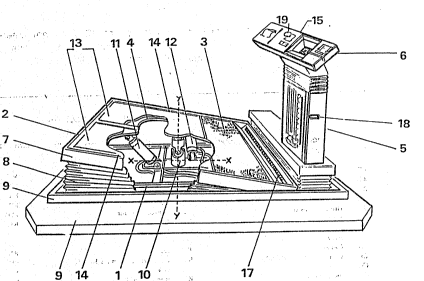
Referring to Fi.gure 1, the aid comprises a
~ rectansular base l having a tiltable platform 2 providing a
; : :
S;U13STITU TE SHEE~T
.. , ~ -,
. . . ~ ~ . , .
WO91/02~70 I PCT/GB90/01243
20~4~%~ 4 f'~`
ball playing area 3 and a s~anding are~ 4. A~ one, front,
end of the base a pedestal 5 is provided on top of which a
control panel 6 is mounted.
The platform 2 is of sheet metal aporopriately
stiffened by internal stiffeners (not shown) and a marginal
flange 7 and is mounted on the base 1 via a folding bellows
arrangement 8 to enable tne platfor~ to be tilted as
described hereinafter and prevent the ingress o dirt. As
shown the base, in turn, forms part OL~ or is mounted on, a
plinth 9.
The platform and bellows are cut-away in the Figure
to show that the platform 2 is centrally mo~nted on a
vertically extending universal joint 10 the joint halves of
which are mounted to pivot around two horizontal pivot axes
X, Y whereby tilting can be effected around either axis or a
combination of both to cover a complete range of "lies". At
least one extending telescopic unit 11, 12 respectively is
provided for each pivot axis, each of which is connected
between the base and platform as shown and these units are
connected by ~an appropriate network of pipes if
.hydraulically -or pneumatically operated, or wires if
: electrically operated, whereby they can be moved in unison
by different amounts under the control of suitable control
means to set the angle of tilt required for the platform 2.
A rubber mat 13 or similar is provided over the standing
2S
..~ area 4 and is~marked.with two outlines 14 to define the foot
positions of the user. A control device, which may
~conveniently be in the form of a joystick 15 is provided on
~. the panel.which is operative through a suitable control
SUE35Til~UTE sHEE~T
::
,. - . - , .... ., . , . ~ - . .; ~.
WO9l/02570 ? 0 6 ~ 8 2 2 PCT/GBgo/01243
5 ~; ~3 :
circuit (n~t shown) to move the platform 2 as required by
the user, in which case a scale (not shown) may be provided
to give ~he user a visual indication of the tilt angle set.
Pressure sensing devices (not shown) are provided
beneath the outlines 14 of the standing area 4, which are
operative throuyh a suitable comparator circuit ~not shown)
to sense the weight distribution between the golfer's f~et
when he addresses the practise ball and the weight
transference durin~ his swing, and to pass this information
lO to a balance indicator which in this embodiment comprises a
strip 17 of L.e.d's or similar visual indica~ors as shown
along the front of the platform 2.
As mentioned hereinbefore, a chart strip (not shown)
may also be provided to show the preferred weight
15 distribution for comparison.
In this embodiment, a computer/CPU interface port 18
is provided on the pedestal 5 ~or the control panel if
preferred) for connection to a Computer to enable the user
to play a simulated round of golf as mentioned hereinbefore.
Also, a coin ànd/or card meter l9 may be provided by
2d
removable squares of "grass" of different height to simulate
fairway, semi-rough and rough, as required. Alternatively,
the different sufaces could be provided on three sides of a
vrota~able drum ~not shown) mounted beneath the platform 2 in
which case the appropriate surface would be rotated into
position by a suitablè operating member.
When not in use, the complete unit described above
can be closed-off and locked by a pair on interfitting
covers~20 as shown in Figure 2
SUBSTlTlJT SI JI~ET ~ ~
... ... . .. .
WO91/02~70 ~ , PCT/GB90/01243
2~6~2~ 6 . t-`
Re~erring to Figure 3, the plat~orm 2 is shown
tilted for practising
(A) standing below the ball,
(B) standing above the ball,
(C) an uphill lie, and
(D) a downhill lie.
.
.
, ., . .. . . :
. .
: 20~ ~
- :' ' ' .
.. ..
. , , .;
:: ~; , ; . .,.. , .~.......... . . . .
., " . ~, " ., ~ . .
. . . ; . . . ~ . .
'. ~
3BSTI~UTESHIE~ :
:::