Note : Les descriptions sont présentées dans la langue officielle dans laquelle elles ont été soumises.
WO 91/19917 PCT/US91/02810
2065009
-1-
REINFORCED ANTI-BACKLASH NUT
Field of the Invention
This invention is in the field of anti-backlash nuts
which are designed to provide uniform translational
05 movement along a threaded lead screw, in either direction
in response to relative rotational movement between the
nut and screw and, more particularly, relates to the
reinforcement of said nuts.
Background of the Invention
In many applications, it is important to drive an
element of a machine along a lead screw with accurate
positional repeatability and constant drag torque in both
forward and reverse directions. Data printers and x-y
tables, used as peripheral equipment in the computer
industry, for example, have such requirements.
Positioning devices designed to meet these require-
ments have been proposed, and many of these employ an
anti-backlash nut to achieve the positional accuracy
along the screw which is required. Examples of two such
anti-backlash nut assemblies which have been proposed are
described in the patent literature as follows.
In U.S. Patent Ho. 3,656,358, issued to Kopp, a
linear positioning device is disclosed which is stated to
have an improved collar for use with a comparatively
inexpensive rod having multiple grooves. The collar is
telescoped over and adapted to be translated back and
forth relative to the elongated rod. This collar
includes cants-levered fingers which are resiliently
WO 91/19917 ~ PCT/L'S91 /0281 Q
0650 09
-2-
wedged into angularly spaced grooves formed in the rod to
preload the collar onto the rod and prevent rotational
play from developing between the two. In a specific
embodiment, the collar is telescoped onto a rod in the
05 form of a splined shaft while in another embodiment, the
collar is a nut threaded onto a screw with multiple
threads.
In U.S. Patent No. 3,997,269, issued to Linley, an
anti-backlash, self-aligning nut construction with.
specially constructed tubular nut bodies which co-act
with concentric spring sleeves is described. The nut
bodies, in general, each have a pair of spring-biased
elements provided with internal thread formations adapted
for engagement with the external threads of a screw. In
one embodiment, a self-aligning spring sleeve is provided
having solely three pairs of oppositely-disposed trans-
verse slots to obtain the desired aligning features. The
nut body has a base portion which is separated from the
spring-biased elements by means of two transverse slots
which, together with an adjacent pair of slots in the
spring sleeve, form in effect a universal joint. One of
the remaining slot pairs in the sleeve is oriented
circumferentially with respect to the first pair by an
angle of 90', with a third pair of slots being circum-
ferentially aligned with the first pair.
More recently, an anti-backlash nut having
oppositely-directly longitudinal flexure members has been
disclosed in U.S. Patent No. 4,210,033, which issued to
the present inventors. This anti-backlash nut has a
continuous portion extending longitudinally from one end
WO 91/19917 PCT/US91/02810
-3- 2065009
of the screw to the other. In addition, there are at
least two, and usually more, oppositely-directed longi-
tudinal flexure members which have one end fixed to the
anti-backlash nut and one end free-floating. The
05 oppositely-directed longitudinal flexure members are
biased towards the screw by one or more radial springs or
other means for biasing.
Yet another anti-backlash nut is disclosed in our
U.S. Patent No. 4,249,426, reissued as RE. 32,433, dated
June 9, 1987.
This patent discloses an anti-backlash nut which.has
one or more longitudinal flexure members with one end of
each member fixed and one end free floating in cantilever
fashion. The nut, including the flexure members, under-
goes translational movement along a threaded shaft or
lead screw. Each longitudinal flexure member has a ramp
at its free-floating end. The nut is surrounded by an
annular pressure applying ring which derives its force
from a compression spring. The ring is constantly urged
against the ramps which, in turn, creates radial force
vectors to maintain the internal threads formed on the
flexure members in contact with the threads of the shaft
during operation and even after the nut has become worn.
The threads on the shaft are in the form of a helix,
as are the mating threads on the interior of the flexure
members. When a load is placed on the nut, as for
example, when it is attached to a carriage or printer,
there is a substantial force component acting axially of
the shaft or lead screw and bearing on the threads of the
flexure members. The axial force translates into two
WO 91/19917 - - PC'T/L'S91 /0281 ('
-4-
force vectors, one in the axial direction of the shaft
and the other normal thereto, tangential to the shaft.
This induces the cantilever mounted longitudinal flexure
members to deflect in a direction normal or tangential to
OS the axis of the shaft. This can induce unwanted
backlash.
It is, therefore, an object of the present invention
to provide an anti-backlash nut having longitudinal
flexure members and means for providing structural
rigidity to the members to counteract unwanted resultant
tangential forces due to load on the nut.
Summary of the Invention
The invention resides in an anti-backlash nut which
moves along a lead screw in either of two longitudinal
directions. The screw has an external helical thread and
the nut has internal mating threads. The nut includes at
least one longitudinal flexure member which has one end
fixed to the nut body with the other end free floating.
The longitudinal flexure members) have inclined ramps on
their outer surfaces. The ramps extend radially out-
wardly in a direction away from the fixed end.
An annular member surrounding the nut body applies
an external force radially inwardly to each of the ramps,
the force being substantially constant in either dir-
ection of movement of the nut. The annular member is
urged by a compression spring into engagement with the
ramp(s). The axial force applied to the ramp urges the
internal threads of the flexure members constantly into
engagement with the external threads of the shaft to
eliminate backlash.
WO 91/19917 PCT/US91 /02810
'S- 2065009
To add structural rigidity to the flexure members
and to counteract force acting in a direction which is
tangential to the longitudinal direction of movement of
the nut, cooperating spline means are provided on the
05 longitudinal flexure members and the annular force
applying member.
The spline means include a longitudinal groove in
each of the flexure members extending parallel to the
axis of the screw and a complementary mating longitudinal
ridge projecting from the annular force supplying member
engageable within the groove.
Alternatively, the spline means may include a:
projecting longitudinal ridge on each flexure member also
extending paralle to the axis of the screw and a comple-
mentary mating longitudinal groove in the annual force
applying member engageable within the groove.
In both of the embodiments, the tangential force
vector applied to the longitudinal flexure members is
counteracted by the annular force applying member
surrounding the flexure members due to its rigidity and
its resistance to tangential compression.
The above and other features of the invention,
including various novel details of construction and
combinations of parts will now be more particularly
described with reference to the accompanying figures and
pointed out in the claims. It will be understood that
the particular reinforced anti-backlash nut embodying the
invention is shown by way of illustration only and not as
a limitation of the invention. The principals and
features of this invention may be employed in varied and
numerous embodiments without departing from the scope of
the invention.
WO 91/19917 PCT/US91 /0281
-6-
2p65449
Description of the Drawings
Figure 1 is a perspective view of an anti-backlash
nut representing the prior art.
Figure 2 is a side elevation of the prior art
OS anti-backlash nut mechanism shown under load.
Figure 3 is a force diagram of the prior art
mechanism under load.
Figure 4 is a perspective view of one embodiment of
the present invention.
Figure 5 is a perspective view of a second embodi-
ment of the present invention.
Detailed Description of the Invention
Figure 1, is similar to Figure 9 of our prior U.S.
Patent 4,249,426, reissued as RE. 32,433 and represents
the prior art nut. Figure 2 shows the nut in schematic
form attached to a load mass M.
Referring to Figures 1 and 2, the nut is generally
designated 2, and has a face plate 4, which contains
equally spaced attachment holes 6, so that it can be
attached to an element to be driven (i.e., the load),
such as by bolting. The nut has a circumferentially
continuous portion 8 at the face plate end and a
segmented circumferential portion, generally indicated 9,
at the opposite end. The nut 2 is connected by threads
to a lead screw 3.
Three longitudinal flexure members 10, 12 and 14,
separated from each other by gaps 11, extend outwardly
from the circumferential continuous portion 8. The
circumferential portion 9 at the free end of the nut is
WO 91/19917 PCT/US91/02810
-'- 2065009
made up of three segments, one at the end of each longi-
tudinal flexure member 10, 12 and 14 which, respectively,
have ramps 16, 18 and 20, near the outside surfaces of
their free floating ends. The circumferential diameter
05 of the segmented portion 9 is greater than that of the
portion 8.
An axial compression spring 3o surrounds the anti-
backlash nut and is held in compression between the face
plate 4 and a ring or annular force applying member.32,
which is initially located at the base of the ramps 16,
18 and 20. The ring 32 will slide up the ramps 16, 18
and 20 under the axial force supplied by the spring.30.
This urges the flexure members 8, 10 and 12, axially
inwardly at all times toward the axis alpha of the lead
screw 3 in a continuing manner to accommodate wear and,
thus, eliminate backlash. As thus far described, anti-
backlash nut is operationally the same as in our reissue
patent, RE. 32,433.
The anti-backlash nut is hollow and inwardly
threaded, as indicated at 40 in Figures 1 and 2. Its
threads 40 are in engagement with threads 42 on the lead
screw 3. Rotation of the lead screw in either a clock-
wise or counter-clockwise direction causes the anti-
backlash nut to translate without rotation lengthwise of
the screw 3 and when the face plate 4 is attached to a
load, it causes the load to reciprocate relative to the
axis~alpha-of the screw.
Referring particularly to Figures 2 and 3, when, for
example, the lead screw 42 is rotating in a clockwise
direction with a load mass M secured to the face plate 4,
WO 91/19917 PCf/US91 /02810
~~6~p 09
the nut and the mass 4 are moved from right to left, as
viewed in the figures. An axial load La is delivered to
the nut by the threads 43 of the lead screw 3. Since the
threads are helical about the axis alpha, they are
OS inclined at an angle to the axial load La.
In Figure 3, the reactive forces to the load will be
seen acting on the interior threads 40 of the longi-
tudinal flexure members 10, 12 and 14. There is a
reaction force vector Fr acting normal to the threads 40
on the flexure members and longitudinal force vector F1
parallel to the axis alpha and a normal force vector Fn
acting at right angles to the axial load. The normal
force vector Fn causes the flexure members 10, 12 and 14
to be bent or induced away from the parallelism with the
axis alpha in the direction of the arrow designated
"direction of induced bending". This force is inclined
to separate the threads 40 on the inner side of the
flexure members 8, 10 and 12 from the threads on the lead
screw 42, with a potential result of induced backlash.
Thus, there is a component of force acting on the flexure
members in a direction tangential or normal to the rotat-
ional axis alpha of the lead screw. This would cause the
anti-backlash nut, generally made of plastic,
to wear more rapidly than desired if not rectified.
The problem is overcome in the following manner:
reenforcement is applied to the individual flexure
members 10, 12 and 14 in the form of spline means which
extend parallel to the rotational axis alpha of the lead
screw, which is also the central axis of the anti-
WO 91/19917 PCT/LJS91/02810
-g-
2065009
backlash nut. The spline means are spaced radially
outwardly of the axis alpha.
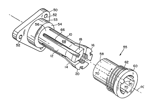
As will be seen in Figure 4, an anti-backlash nut
will be seen as having a face plate 50, which is sub-
05 stantially triangular in shape, although it may be any
convenient shape as determined by the load to which it is
to be attached. It includes holes 52 for securing it by
bolts to the load. There is a cylindrical projection 53,
having a flat face 54, which is normal to the axis alpha.
Flexure members 10, 12 and 14 extend from circum-
ferentially continuous portion 56 of the nut and include
ramps 16, 18 and 20, as in the prior art.
A force applying sleeve, generally indicated 55,
is hollow and has a cylindrical portion 58, and a collar
60. A compression spring 62 surrounds the cylindrical
portion 58 and abutts the collar 60 and when the sleeve
55 is assembled over the flexure members 10, 12 and 14.
The opposite end of the spring abutts the face 54 on the
projection 53 or the face plate 50, depending on the
diameter of the spring. Under the force of the com-
pression spring 62, the face of the collar of the sleeve
55 is urged continuously against the ramps 16, 18 and 20
to cause the flexure members 10, 12 and 14 to be con-
stantly urged inwardly toward the axis alpha to reduce
backlash between the threads 40 of the anti-backlash nut
and the threads 43 of the lead screw 3, which is not
shown in Figures 4 and 5.
The spline means comprise, in part, longitudinal
grooves 66 formed in the surface 68 of each of the
longitudinal flexure members 10, 12 and 14 and extending
WO 91/19917 PCT/US91 /0281
2~65p p9
-lo-
parallel to the axis alpha. When the sleeve 55 is fitted
over the flexure members 10, 12 and 14, mating, parallel
projecting ridges 70 formed on the inside of the screw 55
are received and slide in the longitudinal grooves 66
05 which are located at the same angular spacing relative to
the axis alpha, as are the ridges 70. Thus, as the axial
load La is applied, the resultant normal force vector Fn,
which induces bending of the flexure members 8, to and 12
in a direction tangential to the axis alpha, is counter-
acted by the ridges 70 on the sleeve 55 preventing the
flexure members from being displaced. The sleeve.55
surrounding this flexure member resists displacement to
its rigidity and its resistance to tangential
compression. This not only increases wear life of the
product, but prevents inadvertent backlash from being
created.
Another embodiment of the invention is seen in
Figure 5, wherein the spline means include longitudinally
extending parallel ridges 80 on each of the flexure
members. They extend parallel to the axis alpha and are
located radially outwardly thereof. There is a mating
complementary longitudinal groove 82 for each of the
ridges spaced around the axis alpha uniformly and pro-
jecting inwardly from the interior circular surface 84 of
the force applying sleeve 55. There are ramp portions 86
on the ridges which are the equivalent of the ramps 16,
18 and 20 of the Figure 4 embodiment. The ridges 80
engage within the grooves 82 when the sleeve 55 is
assembled over the flexure members and as in the Figure 4
embodiment. The splined sleeve grooves and ridges
WO 91/19917 PCT/US91 /02810
-11- 20650 pg
prevent the flexure members, under the induced direction
of bending, from deflecting out of parallelism with the
axis alpha.
In all other respects, Applicants' new anti-backlash
05 nut mechanism counteracts backlash by continuously urging
the ramps 16, 18 and 20 on the ramps 86 flexure members
inwardly to maintain the interior threads 40 in engage-
ment with the threads 42 of the lead screw. When
assembled the generally cylindrical force applying sleeve
55 fits over the flexure members with its left-hand (as
viewed in the figures) end close to or abutting the face
54 on the cylindrical portion 53 of the face plate~50 or
on the face plate itself.