Note : Les descriptions sont présentées dans la langue officielle dans laquelle elles ont été soumises.
W091/06018 ~ 3 PCT/GB90/01549
..
:., -- 1 _
OBSTRUCTIO~ DETECTION APPARATUS
. __
This invention relates to obstruction
~` detection apparatus and in particular it relates to
apparatus for the detection of obstructions in the
path of moving bodies such as moving doors on lifts
(elevators) or trains.
Such doors arG often controlled
automatically and should be able to detec~, the
presence of an obstruction such as a boà~ ir. their
path and cease their motion. It is imporuant with a
lift door to ensure that the door closes ~eforc the
lift is raised or lowered, but also to ersure that
- the door does not hlt or even frighten a ?assenger
when closing. I~ is also useful tha~ a~ leas~, two
1, independent protection devices are inc'uded i.^ the
door mechanism, both of which fail to safet~J. .e.
with the doors open. mypically one mecha~ism may use
light beams whilst the other monitors the tor~ue on
the door.
It is preferable to monito.r two aif~Qrer.t
zones of the doorway area, as shown in ~igure a.
- Zone A i`s a thin zone across the opening and
following tha door closing path. An o'cs~ruct cn to
this path causes the doors to be 'hel ' so tha~ a
person can enter o. leave the lift. ~on? ~ is
immediatel~ in front of the door and is broade- than
zone A. It extends for a distance greater tr.an ~he
, stopping distance of the door and prevents the door
from hitting a person going through the entrance.
- 30 According to the present invention there is
' provided an obstruction detection apparatus
comprising a transmitter and a receiver mounted on
one side of a zone to be monitored and having
substantially a commor. ~ield of view ar.d a re~lector
mounted on the other side of the zone and arranged to
...... .............. ............ ~ ~, . . .
- .
W091/060t8 PCT/GB90/01549
6~L3 ,~,
; lie within at least a part of the said field of view
to reflect a signal from the transmitter back to the
receiver, said reflector being endowed with a
reflectivity substantially highe- than any other body
at which the transmitter is normally directed. and
means for detecting a reduction in the signal
received by the receiver to ind cate the presence of
an object interposing the path from the transmitter
~ to the receiver via the rerlector.
Preferably, the reflector lies within only
a part of the ield of view and the apparatus
includes means for detec~ing an incraase in the
signal received by the receiver. whlch increase is
indicative of the entry of an object re'~ive'y close
to the receive. and in the portion of the field o~
view other 'han that in which the reflecto. lies.
According to the present invention there is
- further provided movable door apparatus comprising an
array of transmi~ter/receiver pairs, each pair
comprising a transmitter and receiver in pro~imity
and sharing substantially a common field of view,
respective pairs being mounted in spaced apart
relationship along the leading edge of a door a
re~lection means mounted, ~djacent the surface upon
which the door closes to lie, within at leas~ part of
; the field of view o4 each ~.ansmitter/receiver pair,
tne reflection means having a substantially higher
reflection coefficient than any other surface which
normally lies within said field of view and means
: 30 for detecting a reduction in the signal received by
one or more receivers to indicate the presence of an
object interposing the door and the re41ection
means.
Preferably, the reflection means lies
within only a part o~ the field of view and means are
, :.
. . . . . . .
WO91/06018 2 ~ fi ~ 613 PCT/GB90/01549
- 3 _ -
provided for detecting an increase in the signal
received by one or more receivers to indicate the
entry of an object in the part of the field of view
other than that in which the reflection means lies.
The respective transmitter/receiver pairs -~
may be actuated and monitored in turn by
multiplexing.
Preferably, the reflector or reflection
means is a retroreflecto- but any other r-flector,
such as a plane mi,ror, may be used provided care is
taken to avoid unwanted reflections reaching tne
receiver. Advantageously the retroreflector is in
the form of a screen of spherica' be~ds or
appropriately faceted bodies.
Advantageously, the ~ield of vle~ of ~r- o-
each pair is arranged so that a greate. portion of iv
lies on a chosen side of the doorwa~.
Fmbodiments of the invention wi l now be
described, by way of example only, with reference to
the accompanying diagr~mmatic drawings, in which:
~igure 1 shows a plan view o~ a schematic
lift door apparatus:
?igure 2 shows a front view of tne door
apparatus:
Figure 3 shows a plan view of a further
embodiment of the presen' invention: and
~igure a shows the zones in a doorway which
it is desirable to monitor.
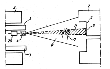
Refer.ing to Figures 1 and 2 a lift door I
is mounted adJacent a lift frame 2. Further doors 3
are provided at each landing and, in use, both a
respective landing door 3 and the lift door 1 must be
open before a passenger can enter or leave the lif~.
Mounted in vertically spaced apart relationship on
the door are a plurality of transmitter/receiver
. .
.
:: .
`:
. i
~ . .
W091/06018 PCT/CB90/01549
~6~ 4
pairs 4. These may be of any suitable type such as
infra-red, ultra-sonic, etc., but are arranged such
; that each transmitter and receiver are proximate or
- integrated in one unit and share substantially a
common field of view ~. The transmitter and receiver
are therefore not focussed. On the other side o~ the
door in ~igures 1 and 2 a fixed slam post 5 is shown.
Alterna~ively, this could be another door for a
system which uses two doors in a bi-parting system.
Vertically mounted on the sla~ post 5 is a
long thin ret.oreflective strip 6 approximately
paralle' to the edge of door 1. ~his may com?rise for
e~ample a plurality of corner cubes or could have a
coa~ing of retroreflective paint, of the type
commonl~ used for road signs. An~ other type Or
retroreflective medium may be applied, for example a
screen with tr~nslucen~ spherica beads embedded to
orm an outer edge. Alterna~ively, a reflector such
as a plane mirror may be used. It is desirable that
the re~lector or retroreflector be a substan~ially
better reflector than any other surface in the
surrounding area. The retrore~lector has the effect
of reflecting any radiation back in the direction
~rom which il came. Thus, substan~ial'y all
radiation e~i~ted in the plan (horizontal) angular
region R of ~igure 1 is reflected back onto itself
and hence onto the receiver par~ of transmitter/
; receiver 4. Similarly, any radiation in the vertical
angular region S for transmitter/receiver 4a of
~igure 2 is re lected back onto itself. When an
obstruction such as a hand 7 is placed within the
zone between t-ansmitter/receiver a and
ret~oreflector 6, less radiation is reflected back.
Accordingly, the signal re^eived a~ t.ansmitter/
receiver 4 is reduced. ~his reduction in signal can
WO91/06018 PCT/GBsO/01549
2Q6~613,
-- 5
be detected by standard and known techniques such as
` thresholding or by using comparators or delays for
example, and used to provide a signal to instruct the
door either not to close or, if it is already
closing, to sto~ closing and o?en. Hence any
obstruction in the direct closing path of the door
will immediately inhibit closure of the door.
A thresholding unit 20 is shown in ~ig.l,
which unit receives a signa' from the tr~nsmitter/
receiver pair 4 and, if the signal is less than ~
predetermined threshold and/or greater than a second
predetermined threshold ! outputs a contro' si~na' ~o
inhibit closure, or begin opening the door, ~s
appropriate. Such uni~s are we'l ~nown. OthP- sig-.a'
dPtecting a?paratuses may, of course. be used.
~he transmitte./receiver pairs ~ ar= spa^Pd
by a distance d down the side o door ,.
Advantageously, this distance is around 50 mm which
, i3 approximately the diamete. of a child's wrist so
that any part of a body will normal'y al~ays be in
the field of vision if that body strays within the
closing path of the door. The transmitte./receiver
ai-s are unfocussed and, as showr. in ~i~ure ~.
ove-la? each other. Hence if an object is placed in
f.ont of the retroreflector 6 i~ will usually cause a
reduction in the signals received by a+ leas' two
receivers ~. A hand placed at posi~ion 7b in ~igure 2
will cause a reduction in part o~ the signa' from
transmitter/ receiver 4a and also in part of the
signal from transmitte.!receiver 4b directly above
4a. By measuring the output of each receiver in each
respective transmitter/receiver pair 4 and noting the
relative changes between them, the position of an
obstruction can be detected to a high deg-Pe o
accuracy. ~or instance, if the si~nal a~ receiver 4a
,, ~ . , : .
,
': '
WO 91/OfiO18 PCI/CB90/01549
~,QC~6~3 - 6 -
is reduced by half, and that at receiver ~b by one
quarter, then the object must be between 4a and 4b,
but nearer 4a.
The transmitter/receiver pairs 4 may
preferably be activated in turn, i.e. multi~lexed,
and the received signals compared with each other.
This is especially desirable if reflectors other than
retroreflectors are used, to prevent unwanted
radiation being received.
Although the retroreflective strip i3 shown
- mounted on a slam post i~ may alternativel~ be
~rovided on the edge o~ a door in a bi-~a-+ing
system.
Any radia+ior. from tr~nsmitters 4 which
falls outside the zon~ defined ~y th- ret.orQ~lQcvi~
strip ~ will be either rerlected away by the s~rface
upon which i~ eventually falls or, more typically,
absorbed or greatly attenuated. Thus, if an object
is placed within this region outside the zone defined ~-
by strip 5, the object will, if it is close enough to
the transmitter/receiver pair, reflect radiation back
and will have the effect of increasing the signal
received. Accordingl~, in a zone close to tne
; transmitter/reCeivQr pair and determined b~ the powe-
o the system and the reflec~ivity o~ any
obstruction, the monitored field of view is wider
than that further ~rom the pair and an obstruction
will make its presence felt by an increase in the
signal. Hence, the system according to the invention
automatically monitors two di~ferent zones
simultaneously but independently, avoiding the need
40r two or more different types of sensor. The zones
can correspond to desired zones A and ~ in ~igure ~.
~his bi-æone monitoring is des rabie because the
closing o, a door may be alarming to a passenge-,
:
" ....
WO91/06018 PCT/~B90/01549
_ 7 _ 2~6~3
particularly if it is a very young or very old
passenger who is close to the door, but not directly
in its closing path.
If a li4t is to be used during busy periods
it will often be ~illed to capacity. In such cases
it will usually be necessary for one or more persons
to stand very close to the edge in a corner o3 the
li t. It is undesirable in such circumstances for
the obstruction sensing apparatus to sense such a
person. ~igure 3 shows an embodiment of the
invention in which such detection is avoided by
rotating the field of view of the t.ansmitter/
receiver pairs about a ver+ical axis such thav the
central plane o3 the fle'd of vie~ is a' an angle O
to the closing directior. of the door. mhe angle ^ is
such that the area of devection in which an increase
in signal occurs when an object is placed in tne
field of vie~ is just in front of the car door 1 and
landing door 3. The transmitter/ receiver pairs are
still able to "see" the slam post or second door 5 ?
and hence the retroreflector, and to detect a
reduction in signal indicative of an obstruction in
tne direct closing path. If an objec+ to be detected
enters the detection zone outside that de~.ned by
retroflective strip ~ then an increase in signal is
seen.
A reference transmitter/receiver pair may
- preferably be provided outside the detection zone to
ac+ as a comparison reference for the remaining
pairs. Alternavively, a re~erence signal can be
generated by averaging a'l the received signals.
The present invention avoids the need for
careful focusing of transmitter/receiver pairs since
all the pairs are unfocused and have a conical volume
o vision directed at a ?ar~icular angle. In some
,~
.. .. . . .
.. . ..
-
~ ,:
WO91/06018 ~9j PCTJGB90/01549
applications it is possible to restrict the angle of
vision. This may be achieved by using partially
focused transmitters and receivers or by the use of
shutters for restricting the angle of vision.
Since only a passive retroreflector is
required on the right side of the door in the ~igures
considerable cos' savings are achieved since active
circuits need only be provided on one side of the
door opening. ~hus wires linking the two sides of
the opening are obviated and a reduction in power
supply consumption is achieved.
It is further preferable tha~ the
retroreflector ~ is housed in an identical enclosure
to the transmitte./recelve. circuits. These cir^uits
are often housed in an elongate channe' shaped member
which extends down the length o~ the door. By also
mounting the retrore~lective means in a similar
member, cost is greatly reduced and the appearance of
,; the system improved. A guarding channel-shaped
member also serves to protect both the transmitter/
receiver pairs and the retroreflective means.
The invention is also applicable in control
or monitoring systems, or with robots, machine guards
and other applications related to conveying or
material handling. The invention can also be used in
intruder detection systems.
, ,,,~ ,.
.. . : .......... : ', i. : . ~ ,:
~, . . .