Note : Les descriptions sont présentées dans la langue officielle dans laquelle elles ont été soumises.
20G7035
ATTACHABLE HANDLE
This invention relates to attachable handles for tools
and similar implements. Such devices are known, typically
they consist of a D grip, such as that of a spade, fork, or
snow shovel, having attachment means for tool or implement
having a bar, shank, pole, rod, shaft or tube. Typically
the attachment means are clamping or ~ripping means ~ e
The present invention envisa~es hollow tube means having
female thread means adapted to engage clamping or gripping
means having paired ends havin~ male thread means to fit the
female thread means. Appropriate rotation of the tube
allows tightening or slackening of clamping means around the
bar, shank, shaft, rod, pole or tube. The hollow tube may
form the handle or may rotatably mount a D handle.
Although the invention will be described and referred
to specifically as it relates to hollow tube meansr and
clamping means, mutually engaging by thread means, it will
be understood that the principles of this invention are
equally applicable to similar systems and accordingly, it
will be understood that the invention is not limited to such
systems.
PRIOR ART AND BACKGROUND OF INVENTION
The following US patents describe related devices
2,430,802 - Catlin
2,482,589 - Maguire
2,531,227 - Lubins
2,614,8~ - Citso
3 r 155 r 414 - Bales
4,155,582 - Reisner
4,944,541 - Waldschmidt
Similarly the following Canadian patents teach related
devices
44,544 - r~alsh (1)
121,537 - Hunt et al.
~067D3~
222.536 - Jewell
223,696 - Coleman
~63,357 - ~alsh (2)
1,081,024 - Vaslas
These ~enerally have a D type handle (except Maguire,
which has a cylindrical handle) attachable to a tool shank,
shaft, rod, pole or tube by a variety of clamping and
attachment means, which may be snap on cylindrical (Walsh
(1)), cylindrical with wing portions connected by a threaded
bolt (Jewell, Maguire, 5itso), pivoted cylindrical with win~
portions connected by a threaded bolt (Hunt et al., Catlin),
spike into the shank (Coleman), bolt through the shank
(Walsh (2) and Waldschmidt), two part bolted clamp to fit
specific diameter shank (Lubins), U clamp with semi-
cylindrical seat to fit specific diameter shank (Bales),
serrated shaft engaging portion and screw tightenable
flexible adjustable strap ~Reisner), opposed fixed winged
semi-cylindrical connected by paired threaded bolts
2Q (Vaslas). The handle may fixed with respect to the
attachment means or pivoted by ball joint (Catlin),
rotatable about an axis perpendicular to the shank (Catlin)~
rotatable in the plane of the shank (Hunt et al., Coleman,
Walsh ~2), Lubins, Vaslas, Waldschmidt). None of these
provide a simple effective device for attachment to a
variety of tool shanks.
There are US patents describin~ fruit jar and coffee
pot holders
681 ! 283 - ~aynic~
1,953,238 - Kosanovich
2,428,942 - Po~lein
2,490,838 - Serio (1)
2,554,643 - Serio (2)
3,311,339 - Holton
These describe a band or loop, passed around a
cylindrical object, having its ends secured within a handle.
3 ;~ 7 ~ ~ ~
~ ,,",, .
The ends may be integrally united and threadably received in a nut within the
handle (Waynick), clamped within paired handle parts together so that holes
within the ends correspond and receive a bolt (Kosanovich), snap fitted togetherin a socket in the handle (Poglein), have threaded ends which fit the handle andare secured thereto by an overriding nut (Serio (1~), have ends which fit grooves
in the handle, and are held in place by an overriding nut threaded onto the handle
(Serio(2)), are threaded and received in a recess in the handle, where they are
engaged by a threaded bolt (Holton). Only Kosanovich teaches band or loop
perimeter changes, in the rest the band or loop is rigid as in Waynick, or such
adjustment as is present is to overcome tolerance variation.
It is an object of the invention to provide an improved attachable
handle for tool or similar implement shanks.
SUMMARY OF THE INVENTION
According to the present invention there is provided Kit means for
securing to a round object, said kit means comprising:
a flexible strip to be secured around the object, the strip comprising
opposed terminal means, central means, and opposed connecting means
extendin~ between said central means and said terminal means,
said opposed terminal means having cooperating interlocking
means and opposed outer thread means
said central means having a width greater than said opposed
connecting means and said opposed terminal means
said central means being adaptable to releasably engage said
object,
a saddle comprising
a saddle member having
.
first and second ends
a tapered aperture extending from said first end to said
second end, said aperture having a predetermined diameter at said second end
and a substantially greater diameter at said first end, and
a rim at said first end circumjacent said aperture, and
paired diametrically opposed peripheral curved recesses
extending into said rim toward said second end, and
a stub tube joined to the saddle member at said second end,
said stub tube having a through passage of a diameter substantially equal to said
predetermined diameter,
said flexible strip opposed terminal means when interlocked being
passable through said saddle, and
female thread means to engage said flexible strip thread means
The flexible strip is preferal~ly sufficiently flexible to accommodate
cylindrical bars varying in diameter by a factor of four. The interlocking meansmay comprise projections on one inner surface, and recesses on the other inner
surface adapted to engage the projections.
In the saddle member, each of the curved recesses may have its
smallest radius of curvature at the deepest point of the recess. The radius
increases outward to the largest radius of curvature at the end of the saddle
member. The smallest radius of curvature corresponds to that of the smallest
diameter bar to be engaged by the handle, the largest radius of curvature
corresponds to the largest diameter bar. rreferably circumferential grooves in the
saddle member allow distortion of the end of the saddle member adjacent the rim.
.~.
Q ~ 5
The flexible strip opposed connecting means and the flexible strip
opposed ends when interlocked are passable through the saddle. A female
threaded screw member is present to engage the flexible strip cylindrical screw
threaded means. This female threaded screw member may be a cylindrical tube
5 which preferably has a cylindrical recess to receive the stub tube of the saddle
and female threaded screw means to engage the threaded part of the flexible
strip. The cylindrical tube forms a handle, preferably having a rounded closed
end. The female threaded screw member means may be a nut.
A D handle having a cylindrical tube may be rotatably mounted on
10 the stub tube. The nut preferably has a knurled peripheral surface, and the Dhandle comprises opposed arms inclined to the axis of the D handle cylindrical
tube, the opposed arms being joined by a cross hand grip. More preferably the
arms are inclined at an angle of about 45~ to 55~ to the axis of the D handle
cylindrical tube.
A major advantage of the split ends and connectors of the strip is
that the handle device can be passed around a bar handle, which it attached at
both ends. The strip is virtually infinitely adjustable between its limits. The
saddle allows tight frictional gripping of the bar, and distortion of the recesses to
fit the bar.
20 BRIEF DESCRIPTION OF THE DRAWINGS
Preferred embodiments are indicated in the drawings where:
Figure 1 shows a sectional view of an embodiment of the invention
attached to a tool shank, transverse to the shank;
Figure 2 shows a sectional view of the embodiment of Figure 1,
25 longitudinal to the shank;
.~
Q ~ $
Figure 3 shows a sectional view of the embodiment of Figure 1,
transverse to a tool shank of different size;
Figure 4 shows a sectional view of another embodiment of the
invention attached to a tool shank, longitudinal to the shank
DESCRIPTION OF THE PHt~t~HtL~ EMBODIMENTS
The general description of the invention is now expanded by
reference to the drawings, which illustrate preferred embodiments of the
invention.
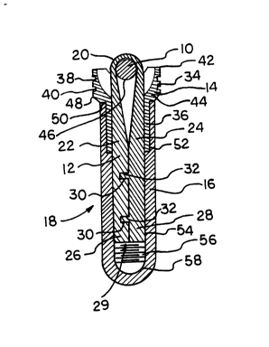
The numeral 10 generally indicates the tool shank, engaged in
combination by flexible strip 12, saddle 14, and internally threaded tube 16,
forming handle attachment 18. Flexible strip 12 has mid portion 20, which is theshank engaging portion, connecting portions 22 and 24, and end which matingly
engage projections 32 of end portion 28. When this matingly engaged end
portions 26 and 28 form cylinder 29 of 3/4 inch diameter and 2 inch length
having a male exterior thread. Connecting portions 22 and 24 taper in maximum
thickness from 11/16 or 3/8 inch adjacent end portions 26 and 28 to about 1/8
inch adjacent mid portion 20, the connecting portions taper a little or not at all in
width, remaining about 11/16 inch wide. Mid portion 20 is 2 1/4 inch long, has
maximum width 1 1/4 inch, which smoothly curves into connecting portions 22
and 24, it has maximum thickness 1/8 inch. Flexible strip 12 is composed of highdensity polyethylene. As would be undcrslood by those skilled in the art, linearhigh density polyethylene, nylon, and other suitable plastic materials, and suitable
commonly available may be utilized for this purpose. Saddle 14 consists of saddle
member 34 and integral stub tube 35 which is rotatably mounted in threaded tube
16. Saddle member 34 has a cylindrical exterior with peripheral grooves 38 and
40, and a tapered interior which extends from rounded edge 42 to tube end 44,
edge 42 has opposed curved recesses 46 to accommodate shank 10, saddle
member 34 also has peripheral bevel 48 and shoulder 50. Tube 36 is 1/18 inch
5 deep with outer diameter 1 inch, and inner diameter 3/4 inch. Saddle member 34is 3/4 inche deep and 1 1/2 inch external diameter, edge 42 is rounded and 1/8
inch thick, recess 46 is 1/4 inch deep and 7/8 inch across of smoothly curvaturewith the radius 1/4 inch at the bottom and 7/8 inch at the edge. Saddle member
34 is preferably composed of high density polyethylene, as would be understood
10 by those skilled in the art, lineal high density polyethylene, nylon and other
suitable plastic materials and suitable commonly available metals, and other
similar materials of similar properties may be utilized for this purpose. Internally
threaded tube 16 has a cylindrical recess 52, to accommodate stub tube 36, the
cylindrical interior of 54 of threaded tube 16 is a female threaded screw 56
extending from recess 52 to rounded end 58. Tube 16 is 4 1/4 inches long, and
has external diameter 1 1/4 inches, internal diameter 3/4 inch, recess 52 has
internal diameter 1 inch and extends 1 1 /8 inch along tube 16. Internally
threaded tube 16 is preferably composed of high density polyethylene, as would
be understood by those skilled in the art, lineal high density polyethylene, nylon
20 and other suitable plastic ",alerials, and suitable commonly available metals, and
other similar ",aterials of similar properties may be utilized for this purpose.In use strip 12 is unthreaded and placed around tool shank 10, end
portions 26 and 28 are engaged by fitting projections 32 into recesses 30, to
form cylinder 29, saddle 14 is slid over cylinder 29 as is tube 16, which is rotaled
25 threadably engaging cylinder 29. Tube 16 pushes saddle member 14 until it
A
8 ~ Q 3 ~
approaches shank 10, as tube 16 advances saddle 14 which can freely rotate
receives shank 10 within recesses 46 as shown shank 10 is 1/2 inch diameter.
When shank 10 is 1 3/4 or 2 inch in diameter, as in Figure 3, recesss 46 and
saddle member 34 distort to tightly frictionally engage shank 10,9 rooves 38 and5 40, although not absolutely necessary to achieve this end, are preferred as they
make distortion easier. Rounded edges 42 and interior taper of saddle 14 preventdamage to strip 12, when contacting saddle member 34.
In Figure 4, is shown a related embodiment, D handle 60 is held in
place by stop nut 62, D handle includes hollow cylinrical cross ~rip 64, side arms
66, and tube 68, which is swivellably mounted about stub tube 36 of saddle 14.
Cylinder 68 has end washer 70, preferably as shown integral. Stop nut 62 has
flat washer engaging surface 72, knurled cylindrical female threaded portion 76.In use strip 12 is unthreaded and placed around tool shank 10, end
portions 26 and 28 are engaged by fitting projections 32 into recesses 30, to
form cylinder 29, saddle member 14 is slid over cylinder 29 as is tube 68, whichis slid over stub tube 36. Stop nut 62 is rotated threadably engaging cylinder 29.
Stop nut 62 pushes washer 70 and thus tube 68 into saddle 14 which
approaches shank 10, as stop nut 62 advances saddle 14 which can freely rotate
receives shank 10 within recesses 46 as shown shank 10 is 1/2 inch diameter.
Tube 68 is 1 3/8 inch internal diameter and 1 inch internal diameter, washer 72 is
of 1 inch internal diameter and 1/4 inch wide. Arm 66 tapers from 1 1/2 inch to
1 3/8 inch at cross grip 64, which is 1 3/8 inch diameter. Arm 66 is 5 1/2 inches
long, but may be as much as 6 1/4 inches long. The angle of arm 66 to the
center line of cylinder 29 is about 50 degrees with the side closest to shank 10begin slightly less inclined. Stop nut 62 is about 3 1/4 inch in diameter at knurled
.~
~ ~ f~ O ~
portion 74, and has central female threaded passage 3/4 inch in diameter and 1
1/8 inch long. D handle 60 and stop nut 62 are preferably composed of high
density polyethylene, as would be understood by those skilled in the art, linearhigh density polyethylene, nylon, and other suitable plastic materials, and suitable
5 commonly available metals, and other simiilar materials of similar properties may
be utilized for this purpose.
As those skilled in the art would realize these preferred illustrated
dimensions, details and components can be subjected to substantial variation,
modification, change, alteration, and substitution without affecting or modifying
10 the function of the illustrated embodiments. Although embodiments of the
invention have been described above, it is not limited thereto, and it will be
apparent to persons skilled in the art that numerous modifications and variations
form part of the present invention insofar as they do not depart from the spirit,
nature and scope of the claimed and described invention.