Note : Les descriptions sont présentées dans la langue officielle dans laquelle elles ont été soumises.
206936q
This invention relates to contiguous
filterbanks using surface acoustic wave (SAW)
technology and, in particular, to filterbanks that
produce an output signal with amplitude and phase
characteristics to provide a continuous response
across the entire bandwidth of the filterbank. These
filterbanks can provide a range of bandwidth varying
in discrete steps and are sometimes referred to as
bandwidth switchable SAW filters (BSSF).
It is known to have filterbanks containing
filters containing surface acoustic wave technology.
Theoretically, a filterbank should produce an overall
result that is the sum of the results of the
individual filters. In most applications of
filterbanks, it is desirable that the sum of these
results should overlap sufficiently so that the
combined response of the filters is continuous across
the combined bandwidth. In practice, with known
filterbanks, the theoretical response was not
achievable and the combined response was not
continuous across the combined bandwidth or the
amplitude and phase characteristics of all filters do
not track closely over the operating temperature
range. The individual filters of the filterbank for
BSSF filters often require a wide difference of
bandwidths among the individual filters. The
requirement for dissimilar bandwidths conflicts with
that for identical tracking and theoretical responses
have not been previously obtainable in practice.
Further, with dissimilar bandwidths, substantial
amplitude and phase offsets may occur over
temperature.
A filterbank using surface acoustic wave
technology has an input and an output. The filterbank
- 1 --
'~7
2069369
has a plurality of filters, each filter having an
input transducer and an output transducer. Each
output transducer has a separate matching circuit, the
matching circuits of all of the output transducers
being identical to one another, said output
transducers having identical impedances. Each
transducer is formed by a film of metal pattern on a
piezoelectric substrate and has electrodes extending
between two busbars. The input transducers are
interconnected. Each filter has a bandwidth that is
dissimilar from the bandwidth of other filters in the
filterbank. The bandwidth of the filters together
providing an overall bandwidth for the filterbank.
Each transducer has a weighting function, a radiation
conductance, an output amplitude and a capacitance.
The weighting function of each input transducer is
scaled to equalize the radiation conductances and
provide a constant impedance across the bandwidth of
the filterbank. The weighting function of each output
transducer is scaled to equalize the output amplitudes
of all of the output transducers and biased to
equalize the capacitances of the output transducers,
thereby producing matched output signals with regard
to amplitudes and phases with temperature and
producing a continuous response across the bandwidth
of the filterbank.
A method of operating a filterbank using
surface acoustic wave technology where said filterbank
has an input and an output and includes a plurality of
filters, each filter having an input transducer and an
output transducer, each output transducer having a
separate matching circuit, the matching circuits of
all of the output transducers being identical to one
another, said output transducers having identical
-- 2 --
`- 2069369
impedances, each transducer being formed by a thin
film of metal pattern on a piezoelectric substrate and
having electrodes, the input transducers being
interconnected, each filter having a bandwidth that is
dissimilar from the bandwidth of other filters in the
filterbank, the bandwidth of the filters together
providing an overall bandwidth for the filterbank,
each transducer having a weighting function, a
radiation conductance, an output amplitude and a
capacitance, said method comprising scaling the
weighting function of each input transducer to
equalize the radiation conductances and provide a
constant impedance across the bandwidth of the
filterbank, scaling the weighting function of each
output transducer to equalize the output amplitudes of
all of the output transducers and biasing the
weighting function of each of the output transducers
to equalize the capacitances of the output
transducers, thereby producing matched output signals
with regard to amplitudes and phases with temperature
and producing a continuous response across the
bandwidth of the filterbank.
In the drawings:
Figure l(a) is a prior art drawing showing
the theoretical responses in a graph of amplitude
versus frequency of three individual filters;
Figure l(b) is a prior art drawing of a
theoretical composite filter response for a filterbank
based on the combination of the individual filter
responses of Figure l(a);
Figure l(c) is a prior art circuit diagram
for a filterbank containing bandwidth switchable SAW
filters;
-- 3
- 2069369
Figure 2 is a graph of an individual filter
response for a first SAW filter of a filterbank;
Figure 3 is a graph of an individual filter
response for a second SAW filter of a filterbank;
Figure 4 is a graph of an individual filter
response for a third SAW filter of a filterbank;
Figure 5 is a graph showing the overall
combined filterbank response of a filterbank
containing the three filters shown in Figures 2, 3 and
4 in accordance with the present invention;
Figure 6 is a schematic top view of a
filterbank in accordance with the present invention,
said filterbank having three filters containing
transducers of identical structure; and
Figure 7 is an enlarged view of part of a
prior art SAW transducer structure having a split
finger configuration.
In Figures l(a), l(b) and l(c), there is
shown a schematic illustration of BSSF operation. The
transition regions shown in Figure l(a), between
passband and stopband edges, of adjacent filters
overlap and the transition responses add vectorially
to give a continuous overall response. The schematic
illustration is theoretical only and the combined
continuous response has not previously been achievable
in practice. In practice, the transition responses
did not add vectorially to produce the continuous
response shown in Figure l(b) and the response in the
transition regions was always an uneven response.
In a f~lterbank containing filters
constructed and operated in accordance with the
present invention, a continuous response can be
attained over a wide temperature range. With
appropriate software, the responses shown in Figures
-- 4 --
2069~6~
2, 3 and 4 can be achieved. Each of the filters have
dissimilar bandwidths and it can be seen from the
combined response shown in Figure 5 that the
theoretical continuous response shown in Figure l(b)
can be achieved on a practical basis in accordance
with the present invention.
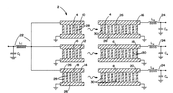
In the schematic view shown in Figure 6, a
three channel BSSF filterbank 2 has three filters 4,
6, 8. Each of the filters 4, 6, 8 has three input
transducers 10, 12, 14 and three output transducers
16, 18, 20 respectively. The three filters 4, 6, 8
have dissimilar bandwidths. The input transducers 10,
12, 14 are connected in parallel with a common input
tuning circuit 22. It is possible to carry out the
invention with the input transducers being
interconnected in various other ways, including a
series connection. The input tuning circuit 22 can
also be referred to as an input matching circuit.
Each output transducer 16, 18, 20 has a separate
matching circuit 24 but all three matching circuits 24
are identical to one another. Each transducer has two
busbars 26 connecting an array of parallel electrodes
28. Each electrode has a break 30 at some position
between the busbars. The electrodes generate or
detect the surface acoustic waves and the pattern of
breaks controls the frequency response of the
transducer.
The transducers of an actual filterbank may
each contain thousands of electrodes. For ease of
illustration, the transducers shown schematically in
Figure 6 have a relatively small number of electrodes.
In the preferred embodiment of the present invention,
the transducer structures for all filters in the
filterbank are identical. In other words, the input
-- 5 --
206~369
transducers have identical structures and the output
transducers have identical structures relative to one
another, though the input and output transducers may
have different structures. The input transducers have
the same number of electrodes with the same widths and
spacings and have the same spacing between the
busbars. The only difference between the input
transducers of the three filters shown in Figure 6 is
the position of the electrode breaks which follow a
different pattern for each of the filters. Similarly,
the output transducers all have the same number of
electrodes with the same widths and spacings and the
same spacing between the busbars. The only difference
between the output transducers of the three filters is
the pattern of electrode breaks. The pattern of
breaks controls the frequency response and therefore
the individual center frequency and bandwidth of each
transducer. Therefore, a non-integral number of
electrodes per wavelength is employed and the waveform
is sampled non-synchronously. There is no detrimental
effect on filter performance and the arrangement
ensures that the properties of the filters are
intrinsically matched.
The prior art "split finger" structure used
in the vast majority of bandpass filter designs is
shown in Figure 7. The same reference numerals are
used in Figure 7 as those used in Figure 6 for those
components that are similar. The electrode period is
an integral number of electrodes per wavelength at
center frequency and for the split finger structure
the electrode period is equal to a quarter of the SAW
wavelength at center frequency ~0. With this
structure, the electrode period is fixed by the center
frequency and varies among the filters within the
-- 6 --
2069369
filterbank. In the present invention, this
relationship is broken and an essentially arbitrary
electrode spacing is chosen, which spacing is
preferably identical for all filters of the
filterbank. While it is preferable that all of the
input transducers have the same structure and all of
the output transducers have the same structure, though
it may be different from that of the output
transducers, this is not essential and differences
between the structures can be overcome by scaling the
input transducers and scaling and biasing the output
transducers to equalize the electrical properties of
the filters and of the matching circuits.
The transducers are formed from thin film
metal (for example, aluminum) patterns on a
piezoelectric substrate, for example, quartz, lithium,
niobate, lithium tantalate. Each transducer has a
weighting function. The weighting function of the
input transducers is scaled to equalize the radiation
conductances and provide a constant impedance across
the filter bandwidth. The weighting function of the
input transducers can also be biased to equalize the
capacitances, but the radiation conductance
equalization leaves the capacitances quite closely
matched and the residual difference in the
capacitances is rarely significant. Therefore,
biasing of the weighting function of the input
transducers is not usually necessary. Thus, even
though the filter bandwidths are quite dissimilar, the
filters can be made to track over temperature and
other conditions. The impedance of a SAW transducer
varies significantly over temperature principally due
to variation in ohmic resistance. When the input
transducer impedances are equalized, identical
-- 7
2069369
matching conditions between transducers are preserved
over temperature.
Since the output transducers have separate
matching circuits, the output transducers must have
identical impedances and must operate with identical
matching circuits. Furthermore, the amplitudes and
phases of the output signals must be precisely
matched. The output amplitudes are equalized by
scaling the weighting functions where necessary and
the capacitances are equalized with bias weighting.
By varying these two parameters, it is possible to
provide matched output signals when operating with
identical matching circuits. Further, since the input
radiation conductances are equalized and the balancing
of the output levels equalizes the transfer
admittances, the output radiation conductances are
also virtually identical. By use of scaling and
biasing, it is therefore possible to ensure that all
properties of the filters are equalized even when the
filters have very dissimilar bandwidths. While the
use of identical transducer structures for all of the
filters is not essential, it is preferred as identical
structures ensure that parasitic effects such as ohmic
resistance are intrinsically matched.
The weighting function of a SAW interdigital
transducer may be defined by a sequence of weights
h(i), where i equals 1,..., N, where N is the number
of electrodes in the transducer. The frequency
response of the transducer is approximately equal to
the Fourier transform of the weighting function. In
the standard implementation, the weights are scaled so
that a break position adjacent to one busbar
corresponds to maximum h(i), while a break adjacent to
the other busbar corresponds to minimum h(i). The
-- 8 --
2069369
electrode breaks are thus spread over the entire
transducer aperture. However, the weights may be
further scaled without affecting the frequency
response. If the weights are all multiplied by an
additional scaling factor of greater than 0 and less
than 1, then the frequency response is unaffected but
the range of the electrode breaks is confined to a
fraction of the aperture and the SAW signal level
launched or received is scaled by a similar amount.
Even when the optimal weighting function for
a transducer has been chosen, it is usually possible
to add additional weighting functions without
significantly affecting the frequency response. In
the present case, this additional weighting, referred
to as bias weighting or biasing, is used to equalize
transducer capacitances. For example, the frequency
response corresponding to a weighting function with
normalized values of +1 and -1 on successive
electrodes would produce a response at the stopband
frequency of the transducer. This frequency is far
removed from the filter passband and is at a point
where SAW propagation is strongly suppressed.
Therefore, the overall-effect on the frequency
response is negligible. The normal weighting function
for a bandpass filter is approximately sin(x)/x
function. The maximum electrode overlaps therefore
occur over the center of the transducer and most of
the capacitance is contributed by the center region.
Given the large ohmic resistances in the patterns, it
is desirable that any equalizing capacitance from the
bias weights should be concentrated at the pattern
center. This may be accomplished by modulating the
alternating bias weights by, for example, a Gaussian
envelope positioned at the pattern center.
_ g _
2069369
In a typical use of the filterbank of the
present invention, the filters will be narrow band
high selectivity devices containing transducers placed
directly in line. The input transducers will employ
"withdrawal weighting" where all electrode breaks are
constrained to be adjacent to one busbar or the other
busbar. This form of weighting means that the
weighting function is only approximated in a
relatively crude manner but the withdrawal weighting
approximation is applied to the scaled weighting
functions in an identical manner to that previously
described.
In the filterbank shown in Figure 6, the net
admittance presented to the input circuit consists of
the combined capacitance and radiation conductances of
the input transducers. The net radiation conductance
is non-zero within the overall filterbank bandwidth
but usually undergoes step changes in value in moving
from one filter passband to the next. This is
undesirable as the input admittance varies across the
band and may produce amplitude tracking differences
over temperature. The scaling of the weighting
functions on the input transducers in accordance with
the present invention is employed to equalize the
radiation conductances. A constant admittance is
therefore presented over the entire bandwidth of the
filterbank and no tracking differences arise from the
input tuning.
For series connected transducers, the
transducer input impedance may be regarded as a
capacitance in series with a radiation resistance. In
this case, the weighting functions are adjusted to
equalize the radiation resistances and maintain a
constant impedance across the band. Whatever the mode
- 10 -
2069369
of interconnection of the input transducers, whether
series, parallel or a combination of the two, the
weighting functions of the input transducers are
always scaled to maintain a constant input impedance
~admittance) across the entire band. In general,
different component values are required for the
various output matching circuits and this is not
acceptable if tracking over temperature is to be
maintained. To overcome this problem, the weighting
function of each of the output transducers is scaled,
and biased as necessary, to ensure that the output
transducer capacitances are equal and that the
transfer admittances are equalized between filters.
This ensures that similar tuning component values are
produced for all output circuits and eliminates any
tracking differences from this source.
While the input and output matching circuits
are single section LC circuits only, more or less
complex matching circuits may be employed according to
their requirements. These matching circuits are
conventional and will be readily apparent to those
skilled in the art. The filterbank shown in Figure 6
shows three filters but the present invention is not
limited thereby and any reasonable number of filters
can be used in a filterbank in accordance with the
present invention. Further, the filters shown in
Figure 6 each have two transducers placed directly in
line with one another. The present invention has been
described as a de-multiplexer which splits a band of
signals into sub-bands. The filterbank can be
operated in reverse as a multiplexer. The outputs
will then become inputs and the input becomes an
output. The teachings of the present invention are
equally applicable to other filter structures
- 11 -
2069369
including, without limiting the generality of the
foregoing, those filters that utilize multi-strip
couplers.
~ 12 -