Sélection de la langue

Search

Sommaire du brevet 2069762 

Énoncé de désistement de responsabilité concernant l'information provenant de tiers

Une partie des informations de ce site Web a été fournie par des sources externes. Le gouvernement du Canada n'assume aucune responsabilité concernant la précision, l'actualité ou la fiabilité des informations fournies par les sources externes. Les utilisateurs qui désirent employer cette information devraient consulter directement la source des informations. Le contenu fourni par les sources externes n'est pas assujetti aux exigences sur les langues officielles, la protection des renseignements personnels et l'accessibilité.

Disponibilité de l'Abrégé et des Revendications

L'apparition de différences dans le texte et l'image des Revendications et de l'Abrégé dépend du moment auquel le document est publié. Les textes des Revendications et de l'Abrégé sont affichés :

  • lorsque la demande peut être examinée par le public;
  • lorsque le brevet est émis (délivrance).
(12) Brevet: (11) CA 2069762
(54) Titre français: COMMUTATEUR DE FIBRE OPTIQUE
(54) Titre anglais: FIBREOPTIC SWITCH
Statut: Réputé périmé
Données bibliographiques
(51) Classification internationale des brevets (CIB):
  • G02B 26/00 (2006.01)
  • G02B 6/35 (2006.01)
  • H04Q 3/52 (2006.01)
(72) Inventeurs :
  • SJOLINDER, SVEN RICKARD (Suède)
(73) Titulaires :
  • TELEFONAKTIEBOLAGET LM ERICSSON (Non disponible)
(71) Demandeurs :
(74) Agent: MARKS & CLERK
(74) Co-agent:
(45) Délivré: 1998-02-03
(86) Date de dépôt PCT: 1990-11-22
(87) Mise à la disponibilité du public: 1991-06-22
Requête d'examen: 1996-12-04
Licence disponible: S.O.
(25) Langue des documents déposés: Anglais

Traité de coopération en matière de brevets (PCT): Oui
(86) Numéro de la demande PCT: PCT/SE1990/000763
(87) Numéro de publication internationale PCT: WO1991/010150
(85) Entrée nationale: 1992-05-27

(30) Données de priorité de la demande:
Numéro de la demande Pays / territoire Date
8904324-4 Suède 1989-12-21

Abrégés

Abrégé français

Commutateur permettant de raccorder sélectivement une ou plusieurs unités d'un nombre n de fibres optiques d'arrivée avec une unité correspondante d'un nombre m de fibres optiques de sortie. Comprend une matrice (1) comportant des émetteurs optiques (2) qui forment un nombre n de rangées et un nombre m de colonnes entre un côté entrée et un côté sortie. Sur le côté entrée, les fibres optiques d'entrée (3) peuvent être déplacées linéairement sur une des rangées d'émetteurs optiques (2); sur le côté sortie, les fibres optiques de sortie (6) peuvent être déplacées linéairement sur une des colonnes d'émetteurs optiques (2). Une fibre optique d'arrivée choisie (3) peut ainsi être déplacée sur une rangée correspondante jusqu'à une colonne d'émetteurs désirée (2), et une fibre optique de sortie (6) d'une colonne correspondante peut être déplacée vers une rangée correspondante d'émetteurs optiques (2) de façon à raccorder l'une à l'autre les fibres optiques choisies.


Abrégé anglais


The present invention relates to a fibreoptic switch for enabling
one or more of n number of incoming optofibres to be connected
selectively with a respective one of m number of outgoing
optofibres. According to the invention, the switch includes a matrix
block (1) having light transmitting devices (2) which extend in n
number of rows and m number of columns between an input side and
an output side. On the input side, the incoming optofibres (3) can
be displaced linearly along a respective row of the rows of light
transmitting devices (2), and the outgoing optofibres (6) on the
output side can be displaced linearly along a respective column of
the columns of light transmitting devices (2?. A selected incoming
optofibre (3) can therewith be displaced along its corresponding
row to a desired column of light transmitting devices (2), and an
outgoing optofibre (6) in a corresponding column can be displaced
to a corresponding row of light trans-mitting devices (2), so as
to mutually connect the selected optofibres.

Revendications

Note : Les revendications sont présentées dans la langue officielle dans laquelle elles ont été soumises.


THE EMBODIMENTS OF THE INVENTION IN WHICH AN EXCLUSIVE
PROPERTY OR PRIVILEGE IS CLAIMED ARE DEFINED AS FOLLOWS:
1. A fibreoptic switch for enabling selective connection of one
or more of an n number of incoming optofibres with a respective one
of an m number of outgoing optofibres, c h a r a c t e r i z e d
in that the switch includes a matrix block (1) having light
transmission devices (2) which extend in n number of rows and m number
of columns between an input side and an output side: in that the
incoming optofibres (3) on the input side are each displaceable
linearly along a respective row of the rows of light transmission
devices (2); in that the outgoing optofibres (6) on the output
side are displaceable linearly along a respective column of the
columns of light transmitting devices (2); and in that a selected
incoming optofibre (3) can be displaced along its corresponding
row to a desired column of light transmitting devices and an
outgoing optofibre (6) in a corresponding column can be displaced
to a corresponding row of light transmitting devices for mutual
connection of the selected optofibres.

2. A switch according to Claim 1, c h a r a c t e r i z e d in
that the light transmission devices (2) are waveguides, optical
fibres or the like.

3. A switch according to Claim 2, c h a r a c t e r i z e d in
that both the incoming and outgoing optofibres (3, 6) are arranged
on slides (4, 7) or corresponding devices which can be displaced
in corresponding guide grooves (5, 8) in the matrix block; and in
that the light transmitting devices (2) terminate in the bottom of
the guide grooves.

4. A switch according to Claim 3, c h a r a c t e r i z e d in
that each slide (4, 7) includes a spring-biased ball (9) which can
engage in a recess (10) provided in each guide groove (5, 8) and
corresponding to each row and column respectively of light
transmitting devices (2), for placing respective optofibres in their
correct positions.

8

5. A switch according to any one of Claims 3 or 4,
c h a r a c t e r i z e d in that the slides (4, 7) can be displaced in the
guide grooves (5, 8) by means of stepping motors or the like.

6. A switch according to any one of Claims 3 to 5,
c h a r a c t e r i z e d in that in cross-section the slides (4, 7) have a
trapezoidal configuration with the base facing towards the matrix
block (1) and in that the guide grooves (4, 8) have a corresponding
configuration.

7. A switch according to Claim 6, c h a r a c t e r i z e d in
that the optofibres (3, 6) exit in the base of the trapezoidal
slides.

Description

Note : Les descriptions sont présentées dans la langue officielle dans laquelle elles ont été soumises.

- . 1 2~6~7~2

A I!l~iOPTIC ~

TECHNICAL FIELD

The present invention relates to a fibreoptic switch which will
enable one or more of an n number of incoming optofibres to be
connected with a respective one of an m number of outgoing
optofibres.

PRIOR ART

A switch affords a possibility of disposing connections in an
ordered array. In the case of opto techniques, the connections
consist of optofibres. Manu~l installation of these fibres in the
absence of any ordered lay-out will ultimately result in an
unbelievable bundle of tangled fibres which is almost impossible
to unravel or which requires expensive de-installation. Attempts
have been made toprovide mechanical solutions which will overcome
these problems. One solution has been to arrange incoming and
outgoing optofibres perpendicularly to one another in one plane,
and to mount raisable and lowerable mirrors or like light deflec-
ting devices at the points at which the fibre axes intersect one
another. The drawback with this solution is that it requires the
provision of many optical components of high precision. Attenua-
tion in signal tr~n! ;ssion is also high~

Other solutions attempted with switches of this kind have included
axranging the incoming and outgoing optofibres in a matrix system.
The switch includes a pluralit~ of optical dividers each connected
to a respective incoming optofibre, a plurality of optical
switches disposed at the matrix intersection points, and a
plurality of optical combiners each connected to a respective
outgoing optifibre. Each switch includes an optoelectric element,
an amplifier and an electrooptic element. Because of the large
number of structural components involved, a switch of this kind is
expensive and complicated, particularly in the case of large
switchs affording many coupling possibilities. The switch also
requires a continuous supply of current.


.
-

,

2~7~2


DISCLOSURE OF T~E INVENTION

The object of the present invention is to avoid the drawbacks of
known switchs by providing an optical switch which is inexpensive
and reliable and to which current need only be supplied when a
change-over i5 made, and which is of simple construction. This
object is achieved with a switch which includes a matrix block
provided with light transmission devices which extend in an n
number of rows and m m ~er of columns between an input side and
an ouL~ side, and in that the incoming optofibres on the input
side are each displaceable linearly along a respective row of
light transmission devices and the outgoing optofibres on the
~uL~uL side are each displaceable linearly along a respective
column of light tr~n, ;ssion devices. This arrangement enables
incoming optofibres to be displaced respectively along their
corresponding rows to a desired column of light trAn! ;~sion
devices and an outgoing optofibre in a corresponding column to be
displaced to a corresponding row of light trAn~ ;~sion devices for
mutual connection of the selected optofibres.

The light transmission devices are preferably waveguides, optical
fibres or the like. The incoming and outgoing optofibres are
advantageously arranged on slides or like devices capable of
being displaced in corresponding guid~ grooves in the matrix
block, said light transmission devices te ;nAting in the bottoms
of respective guide grooves.

Each slide will preferably include a spring-biased ball capable of
engaging a recess provided in each guide groove and corresponding
to each row and column of light transmission devices respectively,
so as to enable respective optofibres to be set to their correct
positions.

An advantage is afforded when the slides can be moved in the guide
grooves with the aid of stepping motors or the like, and, when seen
in cross section, the slides will preferably have a trapezoidal
configuration with the trapezium base facing towards the matrix

2~7~


block. The guide grooves are correspondingly configured and the
optofibres terminate in the base of the trapezoidal slides.

An optical switch constructed in accordance with the invention
provides sevexal advantages. One advantage is that there is no
need to directly remount the connections, i.e. the optofibres,
thereby avoiding tangles. The particular arrangement of a matrix
enables the ~ r of coupling possibilities to be
obt~ine~, i.e. themaximum possible number of combinations between
inputs and ~yu~S.

The use of a wave conductor, optical fibre or the like as the light
transmission devices af~ords the advantage that low attenuation
can be achieved in all set-ups.

Because the optofibres are disposed on slides or the like capable
of being displaced in corresponding guide grooves in the matrix
blocks, there is ob~ine~ a very simple mechanical construction.
The provision on each slide of a spring-biased ball, which can
engage in a recess formed in each guide groove and corresponding
to each row and column of light transmitting devices respectively,
affords the advantage of enabling respective optofibres to be
positioned very accurately.

Because the slides can be displaced in the guide grooves with the
aid of stepping motors or the like, and because the slides have a
trapezoidal cross-section with the base facing towards the matrix
block and because the guide grooves have a corresponding con-
figuration, the optofibres can be accurately positioned with theaid of simple means and the mechanical construction i5 reliable.
No separate means are required to hold the slides in position on
the matrix block.

The invention will now be described in more detail with reference
to an exemplifying embodiment thereof and with reference to the
accompanying drawings.

2~7~


BRIEF DESCRIPTION OF THE DRAWINGS

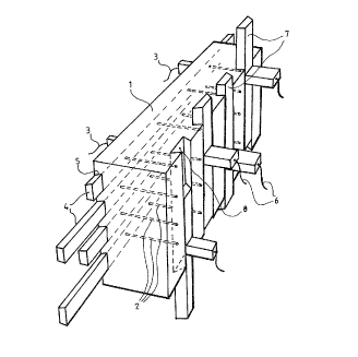
Figure 1 is a perspective view of a preferred embodiment of an
inventive optical switch,
Figure 2 is a sectional view of one part of the switch illustrated
in Figure 1.

BEST MODE FOR CARRYING OUT THE INVENTION

Figure 1 illustrates in perspective a preferred embodiment of an
inventive optical switch~ The switch includes a matrix block 1
having a plurality of light tr~n! i~sion devices 2 which are
arranged in n number of rows and m number of columns. For the sake
of illustration, only four rows and four columns have been shown
on the drawing~ although it will be understood that any number of
rows and columns may be provided and that the number of rows and
columns is only restricted by the size of the switch and by what
can be considered reasonable from the aspect of construction.
Neither need the rows and colum~s be of mutually equal numbers,
as in the case of the illustrated embodiment, but can be varied
independently of one another. The light transmission devices 2
extend through the matrix block 1 from an input side to an output
side and consist of waveguides, optical fibres or simply of a hole
which extends through the matrix block, provided that the block is
narrow.

The ;nc- ing optifibres 3 on the input side are arranged on slides
4 which are inserted in guide grooves 5 in the matrix block 1 and
which can be displaced therealong. The guide grooves 5 are
disposed so that each of said grooves will extend along a respec-
tive row of the n number of rows of light transmitting devices 2,
with the light transmitting devices terminating in the bottom of
respective grooves 5. Similarly, the outgoing optofibres 6 on the
30 vu~u~ side are disposed on slides 7, which are inserted in guide
grooves 8.in the matrix block 1 and can be displaced therealong.
The grooves 8 are disposed perpendicularly to the grooves 5 and
each of the grooves 8 extends along a respective column of the m
nu~ber of columns of light transmitting devices 2, and the light


:

2~7g2


transmitting devicesterminate in thebottom of respective grooves
8. When seen in cross-section, the slides ~ and 7 have a trapezoi-
dal configuration, with the base of the trapezium facing towards
the matrix block 1. The guide grooves 5 and 8 have a corresponding
configuration, so as to guide and hold the slides positively in
the matrix block. Both the incoming and outgoing optofibres 3 and
6 are therewith te ;n~tad in the base of the trapezoidal slides.

The aforedescribed arrangement enables connections to be made
selectively between the incoming and outgoing optofibres. For
instance, the incoming optofibre in row ~ can be moved to the third
column and the outgoing optofibre in column 3 can be moved to row
1, so as to connect these two optofibres together. Similarly,
L~ -in;ng optofibres can be moved selectively to desired rows and
columns respectively, so as to establish the desired connections.

Movement of the slides, and therewith of the optofibres, to the
desired rows and columns can be effected with the aid of stepping
motors or the like (not shown) which drive th slides. In order to
ensure that the correct setting is obtained, each slide 4 or 7 is
provided with a spring-biased ball 9 in the base of the slide,
i -~;ately adjacent the optofibre, as illustrated in ~igure 2,
which is a sectional view of part of a guide groove 5 or 8 in the
matrix block and a part of a corresponding slide 4 or 7. Each guide
groove 5 or 8 is provided with corresponding recesses 10 in which
the spring-biased ball 9 can engage and which are located imme-
diately adjacent the mouths of the light transmission devices 2.This arrangement enables movement of respective slides to be
accurately controlled, so that the optofibre and the light trans-
mitting device will be in alignment with one another, therewith to
achieve the best possible light transmission and the smallest
possible attenuation.

It will be understood that the aforesaid optofibres, both the
incoming and the outgoing fibres, may also include groups of
optofibres, such as band fibre cable having, for instanca, eight
fibres, in which case e~ch incoming fibra group can be connected
to an outgoing optofibre group.

6 2~7~2

It will also be understood that the invention is not restricted to
the aforedescribed and illustrated embodiment, and that modifica-
tions can be made within the scope of the following Claims.

Dessin représentatif
Une figure unique qui représente un dessin illustrant l'invention.
États administratifs

Pour une meilleure compréhension de l'état de la demande ou brevet qui figure sur cette page, la rubrique Mise en garde , et les descriptions de Brevet , États administratifs , Taxes périodiques et Historique des paiements devraient être consultées.

États administratifs

Titre Date
Date de délivrance prévu 1998-02-03
(86) Date de dépôt PCT 1990-11-22
(87) Date de publication PCT 1991-06-22
(85) Entrée nationale 1992-05-27
Requête d'examen 1996-12-04
(45) Délivré 1998-02-03
Réputé périmé 2000-11-22

Historique d'abandonnement

Il n'y a pas d'historique d'abandonnement

Historique des paiements

Type de taxes Anniversaire Échéance Montant payé Date payée
Le dépôt d'une demande de brevet 0,00 $ 1992-05-27
Taxe de maintien en état - Demande - nouvelle loi 2 1992-11-23 100,00 $ 1992-08-28
Enregistrement de documents 0,00 $ 1992-12-22
Taxe de maintien en état - Demande - nouvelle loi 3 1993-11-22 100,00 $ 1993-10-13
Taxe de maintien en état - Demande - nouvelle loi 4 1994-11-22 100,00 $ 1994-10-26
Taxe de maintien en état - Demande - nouvelle loi 5 1995-11-22 150,00 $ 1995-10-19
Taxe de maintien en état - Demande - nouvelle loi 6 1996-11-22 150,00 $ 1996-10-10
Taxe finale 300,00 $ 1997-10-22
Taxe de maintien en état - Demande - nouvelle loi 7 1997-11-24 150,00 $ 1997-10-31
Taxe de maintien en état - brevet - nouvelle loi 8 1998-11-23 150,00 $ 1998-11-12
Titulaires au dossier

Les titulaires actuels et antérieures au dossier sont affichés en ordre alphabétique.

Titulaires actuels au dossier
TELEFONAKTIEBOLAGET LM ERICSSON
Titulaires antérieures au dossier
SJOLINDER, SVEN RICKARD
Les propriétaires antérieurs qui ne figurent pas dans la liste des « Propriétaires au dossier » apparaîtront dans d'autres documents au dossier.
Documents

Pour visionner les fichiers sélectionnés, entrer le code reCAPTCHA :


Pour visualiser une image, cliquer sur un lien dans la colonne description du document. Pour télécharger l'image (les images), cliquer l'une ou plusieurs cases à cocher dans la première colonne et ensuite cliquer sur le bouton "Télécharger sélection en format PDF (archive Zip)" ou le bouton "Télécharger sélection (en un fichier PDF fusionné)".

Liste des documents de brevet publiés et non publiés sur la BDBC .

Si vous avez des difficultés à accéder au contenu, veuillez communiquer avec le Centre de services à la clientèle au 1-866-997-1936, ou envoyer un courriel au Centre de service à la clientèle de l'OPIC.


Description du
Document 
Date
(yyyy-mm-dd) 
Nombre de pages   Taille de l'image (Ko) 
Revendications 1994-03-30 2 68
Abrégé 1994-03-30 1 29
Page couverture 1994-03-30 1 17
Dessins 1994-03-30 2 50
Description 1994-03-30 6 283
Page couverture 1998-02-03 2 69
Dessins représentatifs 1998-02-03 1 12
Rapport d'examen préliminaire international 1992-05-27 20 646
Correspondance reliée au PCT 1997-10-22 1 30
Correspondance de la poursuite 1996-12-04 1 32
Taxes 1996-10-10 1 56
Taxes 1995-10-19 1 56
Taxes 1994-10-26 1 55
Taxes 1993-10-13 2 71
Taxes 1992-08-28 1 27