Sélection de la langue

Search

Sommaire du brevet 2070080 

Énoncé de désistement de responsabilité concernant l'information provenant de tiers

Une partie des informations de ce site Web a été fournie par des sources externes. Le gouvernement du Canada n'assume aucune responsabilité concernant la précision, l'actualité ou la fiabilité des informations fournies par les sources externes. Les utilisateurs qui désirent employer cette information devraient consulter directement la source des informations. Le contenu fourni par les sources externes n'est pas assujetti aux exigences sur les langues officielles, la protection des renseignements personnels et l'accessibilité.

Disponibilité de l'Abrégé et des Revendications

L'apparition de différences dans le texte et l'image des Revendications et de l'Abrégé dépend du moment auquel le document est publié. Les textes des Revendications et de l'Abrégé sont affichés :

  • lorsque la demande peut être examinée par le public;
  • lorsque le brevet est émis (délivrance).
(12) Brevet: (11) CA 2070080
(54) Titre français: POMPE DOSEUSE DE LIQUIDE A BEC FIXE
(54) Titre anglais: LIQUID PUMP DISPENSER HAVING A STATIONARY SPOUT
Statut: Réputé périmé
Données bibliographiques
(51) Classification internationale des brevets (CIB):
  • B05B 11/02 (2006.01)
  • B05B 11/00 (2006.01)
  • B65D 47/34 (2006.01)
(72) Inventeurs :
  • BALDERRAMA, MARK A. (Etats-Unis d'Amérique)
  • GROGAN, R. PAT (Etats-Unis d'Amérique)
(73) Titulaires :
  • CALMAR INC. (Etats-Unis d'Amérique)
(71) Demandeurs :
(74) Agent:
(74) Co-agent:
(45) Délivré: 1999-04-13
(22) Date de dépôt: 1992-05-29
(41) Mise à la disponibilité du public: 1992-12-01
Requête d'examen: 1994-06-28
Licence disponible: S.O.
(25) Langue des documents déposés: Anglais

Traité de coopération en matière de brevets (PCT): Non

(30) Données de priorité de la demande:
Numéro de la demande Pays / territoire Date
708,377 Etats-Unis d'Amérique 1991-05-31

Abrégés

Abrégé français

Cette invention concerne un distributeur de liquide à pompe qui a un bec fixe, un piston fixe et un cylindre alternatif, l'ensemble définissant une chambre de pompage à cylindrée variable. Le distributeur comporte un évent de mise à l'air libre du contenant, un moyen d'amorçage de la pompe ainsi qu'un corps de soupape d'admission/refoulement. Il compte un nombre réduit de pièces pour une plus grande simplicité de fabrication et un coût de revient moindre.


Abrégé anglais


The present invention relates to a liquid
pump dispenser which has a stationary spout, a fixed piston
and a reciprocating cylinder therewith defining a variable
volume pump chamber. The dispenser has container venting and
pump priming features, and includes an inlet/discharge valve
housing. the dispenser has a reduced number of parts for
simplicity and economy.

Revendications

Note : Les revendications sont présentées dans la langue officielle dans laquelle elles ont été soumises.


The embodiments of the invention in which an
exclusive property or privilege is claimed are defined as
follows:

1. A liquid pump dispenser comprising, a pump body
mountable in a fluid tight manner on a container of flowable
product to be dispensed, an upstanding stationary pump piston
on said body, a valve controlled inlet within said body, a
manually reciprocable spring biased plunger head having a
plunger skirt in sealing engagement with said piston for
therewith defining a variable volume pump chamber, a
stationary spout on said pump body defining a discharge
passage extending from said pump chamber, a discharge valve
acting between said pump chamber and said discharge passage,
an annular sleeve on said body surrounding said piston in
spaced relationship and therewith defining a vent chamber
openable to the atmosphere, said body having means defining a
vent passage extending from said vent chamber into the
container, an annular vent seal on said plunger skirt in
sealing engagement with an inner wall of said sleeve for
sealing said vent chamber closed in an upper position of said
plunger head relative to said piston, and means on said inner
wall for breaking the sealing engagement between said vent
seal and said inner wall in a lowered position of said
plunger head relative to said piston for venting the interior
of the container to atmosphere.

2. The dispenser according to Claim 1, further
comprising means on an inner wall of said plunger skirt for


breaking the sealing engagement of said plunger skirt with
said piston in the lower position of said plunger head for
establishing communication between said pump chamber and said
vent chamber for expelling any unwanted air from said pump
chamber during plunger head reciprocation.


3. The dispenser according to Claim 1, wherein said
body has a circular valve seat between said pump chamber and
said discharge passage, said discharge valve comprising a
deformable annular valve seal in sealing engagement with said
seat and deforming radially away from said seat in response
to an increase in pressure within said pump chamber.

4. The dispenser according to Claim 1, wherein said
means on said inner wall of said sleeve comprises a vent rib
for deforming said annular vent seal.

5. The dispenser according to Claim 2, wherein said
piston has a piston seal and wherein said means on said inner
wall of said skirt for breaking the sealing engagement of
said plunger skirt comprises a priming rib for deforming said
piston seal.

6. The dispenser according to Claim 1, wherein a
combined inlet valve and discharge valve housing is disposed
within said pump body for defining said valve controlled
inlet and said discharge valve.

7. The dispenser according to Claim 6, wherein said
body has a circular valve seat between said pump chamber and


said discharge passage, said discharge valve comprising a
deformable annular valve seal on said housing, said valve
seal being in sealing engagement with said seat and deforming
radially away from said seat in response to an increase in
pressure within said pump chamber.


Description

Note : Les descriptions sont présentées dans la langue officielle dans laquelle elles ont été soumises.


The invention relates to a liquid pump dispenser
having a minimum of constituent parts and including a
stationary spout, a stationary piston, container venting and
pump priming features, and an inlet/discharge valve housing.
More particularly, such dispenser is of the throttle pump
variety having a positive leakproof vent control.
Known is a liquid pump dispenser disclosed in U.S.
Patent No. 4,402~432 having a pump priming feature and a
positive container vent control for a pump of the pressure
built~up variety having a reciprocable plunger defining a
variable volume slidable relative to the plunger for
controlling the discharge in response to accumulation of
pressure within the pump chamber. The discharge passage
reciprocates with the plunger head.
'~ Also known is a pump dispenser from U.S. Patent
No. 4,218,198 whlch has a stationary spout and a fixed pump
cylinder for the reception of a reciprocating piston. A
circular discharge flap valve is located between the pump
chamber and the discharge passage~ and a separate vent seal
defining a passive vent is provided.
; It is desirable to provide an improved pump
dispenser of the throttle variety having a ; n; Ul.~ number of
parts for economy and simplicity yet avoiding the performance
and operational drawbacks of the known pump structures.
It is therefore an object of the present inven~ion
to provide a liquid dispenser of the throttle pump variety
having a minimum number of parts rendering the pump structure


easy and economical to fabricate and assemble, simple to
operate yet highly reliable in dispensing liquid product
without leakage.
Another object is to provide such a pump dispenser
as having a stationary spout and fixed piston, a positive
container vent control, and inlet and discharge valving
within the pump body.
A further object is to provide such a pump
dispenser as having a pump chamber priming feature, and a
combined inlet valve and discharge valve housing located

within the valve body for defining the valve control inlet
and the discharge valving.
Other objects, advantages and novel features of the
invention will become more apparent from the following
datailed description of the invention when taken into
; conjunction with the accompanying drawings.
Having thus generally described the invention,
reference will be made to the accompany drawings illustrating
embodiments thereof, in which:
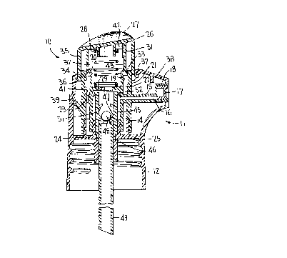
Figure 1 is a vertical sectional view of the liquid

pump dispenser according to the invention; and
Figure 2 is a view similar to Figure 1 showing the
plunger head depressed during pump operation.
Turning now to the drawings wherein like reference
characters refer to like and corresponding parts throughout
the several views, the pump dispenser according to the
invention is generally designated 10 in Figures ~ and 2 and
is of the throttle pump variety given that once primed,

product under pressure is discharged ~rom the pump chamber


upon plunger reciprocation via an open discharge valve
without reliance on pressure build-up causing plunger
shifting to open the discharge.
The dispenser comprises a pump body 11 which
includes a closure cap 12 for threading onto the neck of a
container (not shown) of flowable product to be dispensed.
The cap may, of course, be otherwise snapped into place onto
the container neck.

The pump body further includes a part 13 fixed as
at 14 to the closure cap and having a transversely extending

stationary spout 15 defining a dis~harge passage 16
terminating in a discharge orifice 17 located in a
conventional orifice cup 18.
Part 13 further includes a fixed upstanding piston
19, and a surrounding annular sleeve 21 spaced from the
piston to therewith define an annular vent chamber 22. The
vent chamber communicates with the interior of the container
via a vent opening 23 located in part 13 and a vent opening

24 located in transverse wall 25 of the closure cap.
A plunger head 26 has a finger engageable crown 27

and is mounted on part 13 for axial reciprocation against the
force of a coil return spring 28 extending between the
underside of crown 27 and a transverse wall 29 of part 13.
The plunger has a depending plunger skirt 31
sealingly mounted on piston seal 20 of the piston ~or
therewith defining a variable volume pump chamber 32. The
plunger skirt terminates in an annular deformable vent seal
33 in sealing engagement with inner wall 34 of sleeve 21.


And, the plunger has an outer skirt 35 terminating in a stop
shoulder or rib 36 cooperating with a mating stop shoulder or
rib 37 on a shroud cover 38 fixed o the pump body as at 39.
Upward movement of the plunger head is therefore positively
limited by the interengagement of ribs 36 and 37 which are
designed not be ssalingly engage but to provide communication
between the atmosphere and the undarside of the plunger head.
Vent chamber 22, when opened, communicates with the
atmosphere via ribs 36 and 37. In thP at rest position of
the plunger shown in figure 1, and at the commencement of the

pumping operation, vent seal 33 sealingly engages wall 34 of
sleeve 21. Upon continued downward movement of the plunger
head by the operator, vent seal 33 c:ontacts a vent rib 41
located on wall 34 near the bottom of the vent chamber. Upon
such contact the vent seal is deEormed inwardly such that its
seal with wall 34 is broken, thereby opening the vent chamber
from the atmosphere into the interior of the container to
thereby replenish the dispensed product with air to avoid
hydraulic lock and container collapse during the pump
pressure stroke.

A priming rib 42 is located on inner wall 43 of
plunger skirt 31 near the upper end thereof. Any accumulated
air in pump chamber 28 is thus expelled during the initial
downstroke or downstrokes of the plunger as priming rib 42
contacts resilient piston seal 20 on the piston thereby
causing the piston seal to deform to establish communication
with vent chamber 22. In this condition, shown in Figure 2,
vent seal 33 is deformed by vent rib 41 such any


8~

unwanted air is purged from the pump chamber either to the
atmosphere via the vent chamber or into the container via
vent openings 23 and 24.
A combined inlet and discharge valve housing 45 is
disposed within the pump body and is connected to wall 25 as
at 46. The housing includes an inlet valve seat 47 and an
inlet ball check valve 48 engaging the seat. The housing
suspends a dip tube 49 extending into the container, and has
tiny projections 51 defining a ball cage for the inlet valve.
Located between the pump chamber and discharge
passage 16 is a discharge valve 52 in the form of a
deEormable annular valve seal in sealing engagement with a
circular valve seat 53 defining an inner wall of the pump
body into which discharge passage 16 terminates. The
discharge valve may be secured to or otherwise made integral
with housing 45 and may be located at or near the upper end
of the housing. The discharge valve seal inwardly deforms
radlally in response to an increase in pressure within the
pump chamber during plunger reciprocation to thereby open the
discharge for expelling product under pressure through the
disoharge passage.
Operation of the present dispenser is made manifest
by the foregoing detailed description. Product is dispensed
in a lateral direction during each pressure stroke as the
plunger is manually depressed. To initially prime the pump
the plunger is depressed until the priming rib deforms the
piston seal to purge the pump chamber of any unwanted air to
the atmosphere and/or into the container via the open vent.
The container vent is opened at the end of each plunger


-- 6


stroke as the vent seal on the plunger skirt is deformed by
the vent rib thereby opening the interior of the container to
the atmosphere. Otherwise, in non-use conditions of storage
and shipping, the vent chamber is sealed closed to avoid
leakage through the vent openings. The vent chamber r~ ~; n~
sealed closed at the initiation of the plunger downstroke,
such that should the plunger be inadvertently nudged or the
dispenser dropped against the hard surface, any slight

movement of the plunger head will not cause the vent seal to
break open.
Although a vent rib is disclosed as a means for
breaking the vent seal, other means could be provided within
the scope of the invention. For example, a vent groove could
be provided, a vent opening could be devices such that the
vent seal is caused to slide therealong, or the lower end of
wall 34 could have an enlarged diameter.
Likewise, a vent groove could be substituted for
priming rib 42 without department from the invention. And

inlet valves other than a ball check valve could be provided
within the scope of the invention.

Obviously, many other modifications and variations
of the invention are made possible in light of the above
teachings. It is therefore to be understood that within the
scope of the appended claims the invention may be practiced
otherwise than as specifically described.


Dessin représentatif
Une figure unique qui représente un dessin illustrant l'invention.
États administratifs

Pour une meilleure compréhension de l'état de la demande ou brevet qui figure sur cette page, la rubrique Mise en garde , et les descriptions de Brevet , États administratifs , Taxes périodiques et Historique des paiements devraient être consultées.

États administratifs

Titre Date
Date de délivrance prévu 1999-04-13
(22) Dépôt 1992-05-29
(41) Mise à la disponibilité du public 1992-12-01
Requête d'examen 1994-06-28
(45) Délivré 1999-04-13
Réputé périmé 2000-05-29

Historique d'abandonnement

Il n'y a pas d'historique d'abandonnement

Historique des paiements

Type de taxes Anniversaire Échéance Montant payé Date payée
Le dépôt d'une demande de brevet 0,00 $ 1992-05-29
Enregistrement de documents 0,00 $ 1993-09-24
Taxe de maintien en état - Demande - nouvelle loi 2 1994-05-30 100,00 $ 1994-05-26
Taxe de maintien en état - Demande - nouvelle loi 3 1995-05-29 100,00 $ 1995-05-09
Taxe de maintien en état - Demande - nouvelle loi 4 1996-05-29 100,00 $ 1996-05-13
Taxe de maintien en état - Demande - nouvelle loi 5 1997-05-29 150,00 $ 1997-05-22
Taxe de maintien en état - Demande - nouvelle loi 6 1998-05-29 150,00 $ 1998-04-24
Taxe finale 300,00 $ 1999-01-08
Titulaires au dossier

Les titulaires actuels et antérieures au dossier sont affichés en ordre alphabétique.

Titulaires actuels au dossier
CALMAR INC.
Titulaires antérieures au dossier
BALDERRAMA, MARK A.
GROGAN, R. PAT
Les propriétaires antérieurs qui ne figurent pas dans la liste des « Propriétaires au dossier » apparaîtront dans d'autres documents au dossier.
Documents

Pour visionner les fichiers sélectionnés, entrer le code reCAPTCHA :


Pour visualiser une image, cliquer sur un lien dans la colonne description du document. Pour télécharger l'image (les images), cliquer l'une ou plusieurs cases à cocher dans la première colonne et ensuite cliquer sur le bouton "Télécharger sélection en format PDF (archive Zip)" ou le bouton "Télécharger sélection (en un fichier PDF fusionné)".

Liste des documents de brevet publiés et non publiés sur la BDBC .

Si vous avez des difficultés à accéder au contenu, veuillez communiquer avec le Centre de services à la clientèle au 1-866-997-1936, ou envoyer un courriel au Centre de service à la clientèle de l'OPIC.


Description du
Document 
Date
(yyyy-mm-dd) 
Nombre de pages   Taille de l'image (Ko) 
Revendications 1998-04-29 3 88
Dessins 1998-04-29 1 45
Page couverture 1999-04-07 1 43
Dessins représentatifs 1999-04-07 1 15
Abrégé 1994-01-12 1 17
Page couverture 1994-01-12 1 18
Revendications 1994-01-12 2 87
Dessins 1994-01-12 1 46
Description 1994-01-12 6 251
Correspondance 1999-01-08 1 31
Taxes 1998-04-24 1 27
Lettre du bureau 1992-08-07 1 34
Lettre du bureau 1993-03-12 1 57
Correspondance de la poursuite 1994-06-28 1 49
Lettre du bureau 1994-08-09 1 47
Correspondance de la poursuite 1998-03-13 2 41
Demande d'examen 1998-02-10 1 70
Correspondance de la poursuite 1996-10-23 1 35
Correspondance de la poursuite 1996-09-30 2 53
Demande d'examen 1996-07-16 2 85
Correspondance de la poursuite 1994-06-28 1 49
Taxes 1997-05-22 1 29
Taxes 1996-05-13 1 31
Taxes 1995-05-09 1 32
Taxes 1994-05-26 1 31