Sélection de la langue

Search

Sommaire du brevet 2071156 

Énoncé de désistement de responsabilité concernant l'information provenant de tiers

Une partie des informations de ce site Web a été fournie par des sources externes. Le gouvernement du Canada n'assume aucune responsabilité concernant la précision, l'actualité ou la fiabilité des informations fournies par les sources externes. Les utilisateurs qui désirent employer cette information devraient consulter directement la source des informations. Le contenu fourni par les sources externes n'est pas assujetti aux exigences sur les langues officielles, la protection des renseignements personnels et l'accessibilité.

Disponibilité de l'Abrégé et des Revendications

L'apparition de différences dans le texte et l'image des Revendications et de l'Abrégé dépend du moment auquel le document est publié. Les textes des Revendications et de l'Abrégé sont affichés :

  • lorsque la demande peut être examinée par le public;
  • lorsque le brevet est émis (délivrance).
(12) Demande de brevet: (11) CA 2071156
(54) Titre français: DETONATEUR NON ELECTRIQUE
(54) Titre anglais: NON-ELECTRICAL DETONATOR
Statut: Morte
Données bibliographiques
(51) Classification internationale des brevets (CIB):
  • F42C 19/08 (2006.01)
  • F42D 1/04 (2006.01)
(72) Inventeurs :
  • REKAS, PETER (Autriche)
(73) Titulaires :
  • SCHAFFLER & CO. GESELLSCHAFT M.B.H. (Autriche)
(71) Demandeurs :
(74) Agent: ROBIC
(74) Co-agent:
(45) Délivré:
(22) Date de dépôt: 1992-06-12
(41) Mise à la disponibilité du public: 1992-12-14
Requête d'examen: 1995-04-12
Licence disponible: S.O.
(25) Langue des documents déposés: Anglais

Traité de coopération en matière de brevets (PCT): Non

(30) Données de priorité de la demande:
Numéro de la demande Pays / territoire Date
A 1190/91 Autriche 1991-06-13

Abrégés

Abrégé anglais


Abstract:

A non-electrical detonator featuring, in a sleeve (03) closed at
one end, an igniter (11, 12) which may be provided with a delay
composition (10), which igniter (11, 12) being sealed towards the
open sleeve end by a percussion cap (07) fitted in a retainer
(05), with a fuse (01) inserted at the open sleeve end, at which
position a striking pin (04) for the percussion cap (07) is
arranged such that it is capable of movement. In order to ensure
reliable mobility of the striking pin (04) and maximum conversion
of the pressure energy, the retainer (05) is essentially of
hollow cylindrical design and the striking pin (04) is entirely
located in, and guided by, said retainer (05). Between the
percussion cap (07) and the striking pin (04) can be provided an
elastic body (08) which is penetrable by the striking pin (04)
in the ignition process, and which securely holds the striking
pin (04) in its initial starting position.

(Fig. 1 is proposed for publication)

Revendications

Note : Les revendications sont présentées dans la langue officielle dans laquelle elles ont été soumises.


45542

Patent claims:

1. A non-electrical detonator featuring, in a sleeve (03)
closed at one end, an igniter (11, 12) which may be
provided with a delay composition (10), which igniter (11,
12) being sealed towards the open sleeve end by a
percussion cap (07) fitted in a retainer (05), with a fuse
(01) inserted at the open sleeve end, at which position a
striking pin (04) for the percussion cap (07) is arranged
such that it is capable of movement,

wherein

the retainer (05) is essentially of hollow cylindrical
design, and the striking pin (04) is entirely located in,
and guided by, said retainer (05).

2. A detonator as claimed in claim 1, wherein there is,
located between the percussion cap (07) and the striking
pin (04), an elastic body (08) which is penetrable by said
striking pin (04) during the detonation process.

3. A detonator as claimed in claims 1 or 2, wherein the
percussion cap (07) is firmly held in the retainer (05) by
a supporting tube (06) which surrounds the striking pin
(04).

4. A detonator as claimed in one of claims 1 to 3, wherein the
striking pin (04) is symmetrical in relation to a plane
perpendicular to its axis.

Description

Note : Les descriptions sont présentées dans la langue officielle dans laquelle elles ont été soumises.


The invention relates to a non-electrical detonator featuring,
in a sleeve closed at one end, an igniter which may be provided
with a delay composition, which igniter being sealed towards the
open sleeve end by a percussion cap fitted in a retainer, with
a fuse (primer tube) inserted at the open sleeve end, at which
position a striking pin for the percussion cap is arranged such
that it is capable of movement.

A detonator of the species mentioned above is described in
European patent EP-A1 0253955, particularly in Fig. 4. If the
fuse or primer tube (i.e. the chemical substance contained
therein) of this detonator is ignited, the resultant pressure
wave propagates at high velocity and propels the striking pin
against the percussion cap, whereupon, finally, the igniter is
detonated. The striking pin in this arrangement is guided
partially in the fuse and partially in the percussion cap
retainer. However, this has proven disadvantageous as, when the
detonator is assembled and crimped (insertion of the fuse in the
sleeve employing an interposed elastic plug and subsequent
deformation of the sleeve), the fuse cross section may also
become restricted resulting in inhibition of the mobility of the
striking pin. Moreover, the effective surface area of the
striking pin upon which the gas pressure can ack is limited to
the clear cross section of the fuse.

The object of the invention is to eliminate the above-detailed
disadvantages. This objective is achieved according to the
invention in that the retainer is essentially of hollow
cylindrical shape, and the entire striking pin is located in, and
guided by, said retainer.

As the striking pin is now entirely located in, and guided by,
the hollow cylindrical retainer, there is no longer any dang~r
that its mobility will be adversely affected by the crimping of
the sleeve during detonator manufacture. Moreover, its entire
cross section is now exposed to the pressure wave, thus giving
maximum impact force.

A further disadvantage of the detonator described in EP-A1
0253955 lies in the fact that the striking pin may hit the
percussion cap if the detonator is dropped, thus occasioning
unintentional detonation. This is now avoided according to the
invention in that, between the percussion cap and the striking
pin, there is arranged an elastic body which has to be penetrated
by said striking pin for detonation to occur. This elastic body
retains the striking pin a safe distance from the percussion cap
until the striking pin is propelled forward by the shock wave.
As a result~ accidental, unintentional firing of the detonator
is pre~ented with absolute reliability.

In the case of the known, non-electrical detonators, the
percussion cap is merely inserted in the retainer, in respect of
which the position of said percussion cap is not precisely
defined. This can lead to differing initial clearances between
the striking pin and the percussion cap, and thus to varying
firing behaviour from detonator to detonator. In order to avoid
this disadvantage, it is recommendable, as in the case of the
present invention, to secure the percussion cap in the retainer
by means of a supporting tube which surrounds the striking pin.
The maximum clearance between the striking pin and the percussion
cap is thus clearly defined.

The normal design employed for striking pins in non-electrical
detonators is such that at one end is located the surface which
reacts to the gas pressure, and at the other end is located the
projection which penetrates the percussion cap. When assembling
the detonator, it is therefore necessary to ensure that the
striking pin is positioned the right way round. The additional
time and expense associated with this orientation work can be
avoided if the striking pin is of symmetrical design in relation
to a plane perpendicular to its axis. With such a design, either
end of the striking pin can be inserted first, so that there is
no longer an~ need to ensure that it is being installed the right
way round.


- : . , ~ , ..... . . . .

~ ~ 7 ~


Further details, features and advantages of the invention are
revealed in the following description of an embodiment by
reference to the drawing, in which Fig. 1 shows a longitudinal
section through a non-electrical detonator according to the
invention, Fig. 2 shows a magnified extract of Fig, 1, and Fig.
3 shows a magnified detail of Figs. 1 and 2.

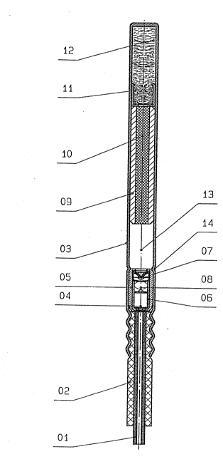
The depicted non-electrical detonator comprises a sleeve 03
closed at one end, in the open end of which sleeve 03 is inserted
a fuse (primer tube) 01 which is fixed in the sleeve open end by
deforming the sleeve 03 against an interposed elaskic plug 02.
In the insertion region of the ~use 01 is located a striking pin
04 arranged in, and capable of movemenk within, a hollow
cylindrical retainer 05. At the base of the retainer 05 is a
percussion cap 07 which is held in position by a supporting tube
06 surrounding the striking pin 04. The striking pin 04 is
favourably designed such that it has characteristics at both ends
which enable a percussion cap to be ignited. This has the
advantage that the striking pin 04 can be installed either way
round. Between the striking pin 04 and the percussion cap 07 is
located an elastic, roughly spherical body 08 which acts as a
compression spring. This elastic body 0~ firmly holds the
striking pin 04 in its initial position (see in particular Fig.
3). ~he retainer 05 and the supporting tube 06 are bordered in
a common operation, as a result of which the diameter of the
supporting tube 06 is reduced such that, during subsequent
assembly work, the fuse 01 does not come into contact with the
striking pin 04. In the sleeve 03, the position of the retainer
05 is fixed between a restriction 14 and the crimp in the region
of the elastic plug 02. The retainer 05 forms a metallically
tight interference fit with the sleeve 03, thus sealing all the
chemical constituents of the detonator. In the space betw~en the
retainer 05 and the base of the sleeve 03 is an igniter
comprising an initial charge 11 and a main charge 12, which
igniter in the present embodiment is preceded by ~ delay
composition 10 contained in a delay element 09, leaving a gas
chamber 13 as a free space.

2 ~


If the fuse 01 is ignited, the pneumatic energy acts like a shock
wave on the striking pin 04 which is propelled in the direction
indicated by the arrow (Fig. 3). In the process, the striking
pin 04 overcomes the resistance of the elastic body 08 and
detonates the percussion cap 07 which, in the ensuing sequence,
ignites the delay composition 10 in delay element 09. The gas
chamber 13, in which the combustion gases gather, remains closed,
as a result of which a high degree of accuracy is achieved in
respect of the delay time. After the pyrotechnic delay
composition 10 has been burnt through, the flame reaches the
initial charge 11 which, as the sequence continues, ignites the
main charge 12, whereupon the detonator explodes.
.~


~!
..,`;
'`


....
~;''

.. . .
.~'..
,~;

f.~'"


''';'

., , ~
, . . . . ,

, .

Dessin représentatif
Une figure unique qui représente un dessin illustrant l'invention.
États administratifs

Pour une meilleure compréhension de l'état de la demande ou brevet qui figure sur cette page, la rubrique Mise en garde , et les descriptions de Brevet , États administratifs , Taxes périodiques et Historique des paiements devraient être consultées.

États administratifs

Titre Date
Date de délivrance prévu Non disponible
(22) Dépôt 1992-06-12
(41) Mise à la disponibilité du public 1992-12-14
Requête d'examen 1995-04-12
Demande morte 2000-03-01

Historique d'abandonnement

Date d'abandonnement Raison Reinstatement Date
1999-03-01 R30(2) - Absence de réponse
1999-06-14 Taxe périodique sur la demande impayée

Historique des paiements

Type de taxes Anniversaire Échéance Montant payé Date payée
Le dépôt d'une demande de brevet 0,00 $ 1992-06-12
Enregistrement de documents 0,00 $ 1992-12-15
Taxe de maintien en état - Demande - nouvelle loi 2 1994-06-13 50,00 $ 1993-07-19
Taxe de maintien en état - Demande - nouvelle loi 3 1995-06-12 100,00 $ 1995-06-06
Taxe de maintien en état - Demande - nouvelle loi 4 1996-06-12 50,00 $ 1996-06-05
Taxe de maintien en état - Demande - nouvelle loi 5 1997-06-12 75,00 $ 1997-06-02
Taxe de maintien en état - Demande - nouvelle loi 6 1998-06-12 75,00 $ 1998-06-01
Titulaires au dossier

Les titulaires actuels et antérieures au dossier sont affichés en ordre alphabétique.

Titulaires actuels au dossier
SCHAFFLER & CO. GESELLSCHAFT M.B.H.
Titulaires antérieures au dossier
REKAS, PETER
Les propriétaires antérieurs qui ne figurent pas dans la liste des « Propriétaires au dossier » apparaîtront dans d'autres documents au dossier.
Documents

Pour visionner les fichiers sélectionnés, entrer le code reCAPTCHA :


Pour visualiser une image, cliquer sur un lien dans la colonne description du document. Pour télécharger l'image (les images), cliquer l'une ou plusieurs cases à cocher dans la première colonne et ensuite cliquer sur le bouton "Télécharger sélection en format PDF (archive Zip)" ou le bouton "Télécharger sélection (en un fichier PDF fusionné)".

Liste des documents de brevet publiés et non publiés sur la BDBC .

Si vous avez des difficultés à accéder au contenu, veuillez communiquer avec le Centre de services à la clientèle au 1-866-997-1936, ou envoyer un courriel au Centre de service à la clientèle de l'OPIC.


Description du
Document 
Date
(yyyy-mm-dd) 
Nombre de pages   Taille de l'image (Ko) 
Correspondance reliée au PCT 1995-04-12 1 49
Correspondance reliée au PCT 1992-09-11 1 29
Lettre du bureau 1992-08-21 1 31
Lettre du bureau 1993-02-17 1 12
Lettre du bureau 1995-05-17 1 72
Demande d'examen 1998-08-28 2 53
Description 1992-12-14 4 192
Page couverture 1992-12-14 1 15
Abrégé 1992-12-14 1 28
Revendications 1992-12-14 1 32
Dessins 1992-12-14 3 109
Dessins représentatifs 1999-07-07 1 26
Taxes 1998-06-01 1 36
Taxes 1997-06-02 1 39
Taxes 1996-06-05 1 99
Taxes 1995-06-06 1 101
Taxes 1993-07-27 1 88