Note : Les descriptions sont présentées dans la langue officielle dans laquelle elles ont été soumises.
UNIVERSAL HOLD-DOWN ASSEMBLY
FOR PUMP ASSEMBLIES AND THE LIKE
Backqround of the Invention
This invention relates to a universally
adjustable hold-down assembly for mounting apparatus on a
support frame, and more particularly for mounting any drive
unit in alignment with its respective driven equipment.
Pump assembly installations frequently include a
separate pump unit and an associated drive unit for driviny
the pump unit. The pump unit and the drive unit are
provided with casing feet or the like having a plurality of
mounting holes to facilitate mounting of the pump unit and
the drive unit on a common support frame. Typically, the
pump unit and the drive unit are attached to the support
frame by bolts which pass through the mounting holes and
through holes in the support frame. For proper operating
of the pump assembly, it is essential that the shaft of the
pump be aliyned coaxially with the shaft of the drive unit.
Thus, some latitude is required in the design of the pump
unit and driver mounts to accommodate pump units and drive
units having different mounting centers. For example, slots
may be provided in the mounting feet of the pump unit and/or
the driver. Although such arrangement provides limited
relative adjustment between the pump unit and the driver
during installation, the amount of relative movement
provided may not be sufficient to allow the shafts to be
aligned coaxially. Also, because only limited adjustment is
provided, considerable time may be required to rework
components to avoid bolt binding. This is particularly true
for the case where the pump unit and/or the driver are
replaced with a different unit, in which case the center
lines for the mounting holes for the replacement pump unit
or drive unit may not match those for the original unit
being replaced.
Summary_of the Invention
It is an object of the present invention to
provide an improved mounting arrangement for mounting
`:
apparatus on a support surface, and in particular, apparatus
includiny a drive unit and a driven unit having shafts which
must be aligned coaxially.
Another object of the invention is to provide a
universally adjustable hold-down assembly for use in
mounting apparatus on a supporting frame or the like wherein
the mount is adjustable to be displace~ble in a horizontal
plane over a range of 0 to 360.
These and other objects are achieved by the
present invention which provides a universally adjustable
hold-down assembly for use in mounting apparatus on a
supporting surface wherein the apparatus has a mounting
portion including a plurality of mounting holes to
facilitate mounting on a supporting surface. The hold-down
assembly comprises a support member for supporting the
mounting portion of the apparatus adjacent to one of the
mounting holes in the mounting portion. The support member
has a generally planar top portion having an inner surface
and an outer surface with an aperture through the top
portion. The support member includes a supporting portion
depending from the top portion and adapted to be secured to
the supporting surface, supporting the top portion in a
parallel spaced relationship with the supporting surface
defining a cavity. The hold-down assembly includes further
a rod having first and second ends with a head portion at
its first end and a shank portion, the rod being positioned
: : . ~ .:
with its shank portion extending through the aperture and
the mounting hole and with its head portion located within
the cavity engaging the inner surface adjacent to the
aperture. A retaining means is received on the shank
portion for drawing the head portion into engagement with
the inner surface of the top portion thereby securing the
mounting support member portion. The size and shape of the
aperture enables the rod to be displaceable along radial
lines, in a horizontal plane normal to the axis of the rod
over a range of 0 to 360. The size of the head portion
relative to the size of the aperture is such that the head
portion is maintained in engagement with the inner surface
: ~
2 ~ 7 ~
of the top portion over the full extent of travel of the
rod.
The invention consists of certain novel features
and structural details hereinafter fully descrihed,
illustrated in the accompanying drawing~s, and particularly
pointed out in the appended claims, it being understood that
various changes in the details may be made without departing
from the spirit, or sacrificing any of the advantages of the
Ipresent invention.
jDescription of the Drawinqs
For the purpose of facilitating and
llunderstanding the invention, there is illustrated in the
Iaccompanying drawings a preferred embodiment thereof, from
an inspection of which, when considered in connection with
the followiny description, the invention, its construction
and operation, and many of its advantages will be readily
understood and appreciated.
FIG. 1 is an exploded perspective view of the .'i'''~,.`.~`7,~`'.1,
adjustably hold-down assembly provided by the present
invention, with the support member partially cut away;
FIG. 2 is a simplified representation of a pump
installation including a pump unit and a drive motor mounted
on a common frame, the drive motor being mounted on the
frame by the adjustable hold-down assembly provided by the
present invention;
FIG. 3 is a side sectional view of the
adjustable hold-down assembly shown assembled with the
mounting foot of an apparatus which is mounted on a
supporting frame; and
FIG. 4 is a top plan view of the hold-down and
assembly.
Description of a Preferred Embodiment
Referring to FIG. 1, the adjustable hold-down
assembly 10 provided by the present invention includes a
support member 12, a rod 13, and a retaining device which in
the exemplary embodiment is a nut 14. As will be shown, the
hold-down assembly 10 is universally adjustable. That is,
the rod 13 is movable relative to the support me~ber 12 in
~7~ d4~
r
all directions relative to the centerline of aperture 15 in
the support member, enabling relocation of the mounting
centerline defined by rod 13 over a continuous 360 range.
Referring to FIG. 2, the hold-down assembly 10 is
described with reference to an application for mounting a
pump unit 20 on a frame 21 with a drive unit 22, which may
be a motor or a steam turbine, for example. However, the
hold-down assembly 10 can be used in virtually any
application which requires adjustable mounting of equipment
or devices on a supporting surface, and particularly, in
applications for mounting equipment or devices having shafts
that must be aligned coaxially with one another. More
specifically, the pump unit 20 and drive unit 22, embodied
as a motor, are mounted on a common frame 21 forming a pump
assembly 24. The pump unit 20 has a shaft 20a which is
aligned coaxially with and connected to the drive shaft 21a
of the motor 22 by way of a coupling device 23. In the
exemplary embodiment, the pump 20 is mounted directly to the
frame 21 by way of bolts 26 which pass through mounting
holes, often threaded to secure the bolts 26, (not shown) of
the pump or mounting portion 27. The motor 22 is mounted to
the frame 21 by way of a plurality of the universal hold-
down assemblies 10, two of which are shown in FIG. 2,
provided in accordance with the present invention. A
separate hold-down assembly 10 is provided for each mounting
leg 28 of the drive unit 22. Each mounting leg has a
generally planar horizontally extending mounting portion
28a, as shown in FIG. 3, which has a mounting hole 28b
therethrough.
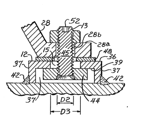
Referring to FIGS. 1 and 3, the support member
12 has a top planar surface 36 and side(s) 37 which depends
from the top. In the exemplary embodiment, the support
member is a generally box-shaped member having four sides
37. However, the support member could be a round cylinder
as well. The top 36 has an outer or upper surface 38 and an
inner or lower surface 39 with aperture 15 therethrough.
Preferably, the aperture is circular in shape. Support
member 12 ls mounted on the frame 21 and permanently secured
2 ~
or fixed thereto in a suitable way as by welding as
indicated at 42 at the lower end of sides 37.
The rod 13 has a head portion 44 which is
generally circular in shape and a threaded shank portion 45,
of circular cross-section, which receives the retaining nut
14 in threading engagement. The head portion 44 is captured
within the box-like structure, defined by the support member
12, and the shank portion 45 projects upwardly through the
aperture 15 and through the mounting hole 28b in the
mounting portion 28a of the motor 22 tF`IG. 3). A shim 48
may be located between the support member 12 and the
mounting portion 28a. The rod 13 is displaceable or
repositionable horizontally relative to the support member
12 to define an adjustable mounting center for the as~embly.
The retaining nut 14 is threaded onto the shank portion 45
and tightened down, as shown in FIG. 3, drawing the head
portion 44 into contact with the inner surface 39 of the
support member 12 to secure the mounting portion 28a of the
drive motor 22 to the frame 21. The end 50 of the threaded
shank 45 is provided with a hexagonal shaped recess 52 to
facilitate tightening of the retaining nut 14. while the
nut 14 is being tightened with a wrench 60, an Allen wrench
62 is inserted into the hexagonal head 52 in the shank of
rod 13 and held, to prevent rotation of the rod 13 while the
nut 14 is tightened down.
Referring to FIGS. 3 and 4, as shown, the outer
diameter D1 (FIG. 4) of the circular head portion 44 is
about twice the outer diameter D2 (FIG. 3) of the rod shank
portion 45, and approximately 1.5 times the diameter D3 of
the aperture 15. Thus, the size of the head portion 44 and
the shank portion 45 relative to the size of the aperture 15
are such that the head portion is maintained in engagement
~ with the inner surface 39 of the top portion over the full
I extent of travel or positioning of the rod ~3 within the
aperture 15. Such a structure provides for universal
adjustment of the position of the rod 13 relative to the
fixed support member 12. In FIG. 4, the rod 13 is
illu:trated at a centered position wherein its axis is
`2 ~
coaxial with the centerline of the aperture 15. The rod 13
is displaceable from this position not only alony or through ;
axes "X" and "Y", but also along radial lines extending at
any angle relative to the axes "X" and "Y". That is, the
shape of the aperture enables the rod to be universally
displaceable or repositional over a range of o to 360O in a
horizonal plane. ~-
l' Thus, in one embodiment of the present invention
there is provided an adjustable hold-down assembly which can
be used in virtually any application which requires
adjustable mounting of equipment or devices on a supporting
surface, and particularly, in applications for mounting
equipment or devices having shafts that must be aligned
coaxially with one another. In one use, for example, one
such assembly is provided for each of the mounting legs of a ~ j~
drive unit, as described for the exemplary application, with
each assembly providing universal adjustability during .:~ ::~
mounting and alignment to the pump unit. This not only
simplifies the installation of the drive unit 22 on the ~ ~ ''.!'
frame 21 but also assures that the shaft 22a of the drive
-,;....
unit 22 is aligned easily and readily with the shaft 20a of
the pump 20.
However, it is within the scope of the present
invention that the adjustable mounting and/or hold-down
. ~ ;-
assembly has application for mounting virtually any drive
unit and its respective driven equipment and for mounting
auxiliary apparatus, such as bearing units, in alignment
with such drive unit and/or driven equipment. Moreover,
although in an exemplary embodiment, the adjustable mounting
and/or hold-down assembly is described with reference to
mounting the drive unit, it is within the scope of the
present invention that the driven equipment and/or the drive
unit and auxiliary apparatus may be mounted by the
adjustable hold-down assembly provided by the present
invention.
~ - , .., ..: .