Note : Les descriptions sont présentées dans la langue officielle dans laquelle elles ont été soumises.
2077019
- 1 -
OPTICAL GLASS FIBER
The present invention relates to a glass fiber for light
transmission, and, more particularly, to an optical glass
fiber having good lateral pressure characteristics and
transmission properties.
To enable the prior art to be described with the aid of a
diagram, the figures of drawings will first be listed.
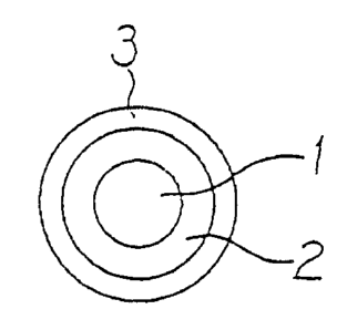
Fig. 1 is a cross sectional view of an optical glass
fiber having a buffer layer and a protective layer,
Fig. 2 schematically shows an apparatus for producing a
coated optical glass fiber, and
Fig. 3 is a graph showing a relationship between Young's
modulus and a cure shrinkage amount.
As shown in Fig. 1, a glass fiber for light transmission,
namely an optical glass fiber, has at least one coating layer
around the fiber, since it is difficult to maintain the
mechanical strength and transmission characteristics of a bare
glass fiber in an as-drawn state. In general, the coating
layer around the optical glass fiber 1 has a two-layer
structure, comprising an inner buffer layer 2 made of a
comparatively soft material and an outer protective layer 3
made of a comparatively rigid material.
When a Uv-curing resin is used for coating the optical
glass fiber, the volume of the coating layer shrinks as the
resin is cured after coating. The resin of the coating layer
shrinks both in the radial direction and the longitudinal
direction of the glass fiber, to generate strain in the glass
fiber. When a resin having a large modulus is used for the
formation of the protective layer, the strain in the glass
fiber is considerable and the light transmission loss
increases. This strain is one of the problems that arise when
the modulus of a coating material is increased. In
particular, the strain generated by the coating layer is a big
problem in maintaining the lateral pressure characteristics,
since a reduction of the diameter of optical glass fibers is
required to increase the density of a cable.
2077019
- 2 -
When an external pressure is applied to the optical glass
fiber in the lateral direction, for example, when the optical
glass fiber is wound around a bobbin, microbends are formed in
the optical glass fiber and, as a result, the light
transmission loss increases. Such properties are referred to
as "lateral pressure characteristics".
One object of the present invention is to provide an
optical glass fiber that solves problems caused by the volume
shrinkage of the coating layer due to resin curing.
Another object of the present invention is to provide an
optical glass fiber that has a small diameter and maintains
good lateral pressure characteristics when it is used in a
high density cable.
According to the present invention, there is provided a
coated glass fiber for light transmission comprising a glass
fiber for light transmission and at least one coating layer
made of a UV-curing resin, wherein the outermost coating layer
is made of a UV-curing resin having a Young's modulus of at
least 100 kg/mm2 and a change of cure shrinkage of 1% or less
after the Young's modulus reaches one tenth of the end Young's
modulus.
Herein, the end Young's modulus is defined as follows:
When a UV-curing resin is irradiated with UV light for a
unit period of time in a unit area, a curing reaction proceeds
in accordance with the exposure dose. The end Young's modulus
is a Young's modulus of the cured resin at completion of the
curing reaction.
The degree of cure shrinkage used herein is defined by
the equation:
Cure shrinkage degree = [ (ds - dt)/ds] x 100 (%) , wherein
dt is the specific gravity of an uncured liquid resin and ds is
the specific gravity of the cured resin. The cure shrinkage
degree varies as the curing reaction proceeds. The cure
shrinkage degree at completion of the curing reaction is
referred to as the end cure shrinkage degree.
-- 2011019
- 3 -
One percent or less of the change of the cure shrinkage
degree means that the difference of the cure shrinkage degree
between a certain point during curing and completion of the
curing reaction is 1% or less. In the present invention, the
change of the cure shrinkage degree is within 1%, preferably
within 0.8%, between the time at which the Young's modulus is
one tenth (1/10) of the end Young's modulus and completion of
the curing reaction.
Hitherto, it has been expected that the light
transmission loss of an optical glass fiber would increase as
the shrinkage stress increases. In general, the shrinkage
stress is expressed as a product of the Young's modulus, the
cure shrinkage degree and the cross sectional area of the
coating layer.
In the actual curing of the resin, the Young's modulus
and the shrinkage during curing of the resin vary with time,
and the shrinkage stress near the end of the curing process at
which the modulus increases will have the greatest influence
on the transmission characteristics of the optical glass
fiber. Therefore, when the UV-curing resin of the coating
layer satisfies the Young's modulus and the change of the cure
shrinkage degree as defined by the present invention, the
light transmission loss is decreased.
As the UV-curing resin that can be used according to the
present invention, any UV-curing resin that has the above
properties may be used. Examples of such UV-curing resins
are UV-curing urethane-acrylate resins, UV-curing epoxy-
acrylate resins, and UV-curable silicone-acrylate resins.
The coated optical glass fiber of the present invention
may be produced by a conventional method, except for the
selection of the UV-curing resin.
PREFERRED EMBODIMENTS OF THE INVENTION
Example
Using the apparatus shown in Fig. 2, a bare optical glass
fiber 1 having a diameter of 125 ~m was fabricated by drawing
a preform 4 in a fiber-drawing furnace 5. Around the bare
optical glass fiber, UV-curing resins were coated by a pair of
2077019
- 4 -
resin coaters 6 and successively cured in UV-light irradiation
apparatus 9 to obtain an optical glass fiber 11 coated with
two layers of UV-curing resin as shown in Fig. 1.
Each irradiation apparatus 9 comprises a UV lamp 7, a
cylinder 8 through which the optical fiber passes, and a
reflector 10. The coated optical glass fiber was wound on a
winder 12.
To form the inner (buffer) layer 2, a UV-curing
urethane-acrylate resin having an end Young's modulus of
0.1 kg/mm2 at room temperature was used. The outer diameter of
the inner layer 2 was 200 ~,m. To form the outer (protective)
layer, a UV-curing urethane-acrylate resin having a different
end Young's modulus as shown in the Table was used. The outer
diameter of the outer layer was 250 ~,m.
In this manner, fiber coated optical glass fibers A to E
were produced.
The lateral pressure characteristics and the transmission
property of each of the coated optical glass fibers A to E
were measured. The results are shown in the Table.
- 2077019
w~
,~ o~ a~
_
O 3 O-~
,p m r~1
N O~ N C' N
M N N M N
3.a ~ 0 0 0 0 0
N G ~..~
p~
C U1 ~ 4J
ra cn O ~D
o
s-r O ~ C
o
E~ rl a1
~
C
O .i.~
-.i c0 E
N c0 ~ 3
~
N h
ri C lf1 ri I~ rl O N
~
\ N N N M N
.
O O O O O
rp N C --
u O ~ ~
E, ~ ~ b
I U
~ QJ
u.i .-I i.
O
.G v -
N UI Z5 w
~ O O GO C~ C~
U U I ~
S.i ~1 ~ r-iri O r-i O
~ tb O
U U x
v o
~ W ~ o o w M
....i a o
CT rl M d' LI7V' Lll
N \ ~ oW
Cf3 'L7 ri
w
aJ ~
Ya ca
d O Op N O
U ~ ~ ~
-ri to oW tI W'1tf1W O
C ,~ v O
W u1 b
N >~
w O 4~N
p, O u-t
?,
C ~U
U1 G ri \ O O O O O
O ~ r1 t~ CO O O tf1 L!1
'yl r~ Cn ri r1 r~ r~
1.-~ .Y
v ~-
C O ~ O
W E ~o O
W
4J
O c~ G7 U D W
Cs, 2
2077019
- 6 -
The transmission loss in a bundle state in the Table
represents the transmission loss caused by the shrinkage
stress of the resin with no lateral pressure on the fibers.
The transmission loss when wound around a bobbin under
tension of 100 g in the Table depends on the lateral pressure
characteristics of the fibers.
Fig. 3 shows the relationship between the Young's modulus
and the cure shrinkage degree of the resin forming the outer
layer. The resin which did not reach the end cure shrinkage
was prepared by curing the resin at a very low dose of
the Uv light.
From the results in the Table and Fig. 3, it is
understood that when the Young's modulus is at least
100 kg/mm2, preferably at least 150 kg/mmZ, and a change of
the cure shrinkage degree is 1% or less, preferably 0.8% or
less, after the Young's modulus reaches one tenth of the end
Young's modulus (fibers C and E), the fiber has good lateral
pressure characteristics.
In a case where the coating layer has more than two
layers, the effects of the present invention can be achieved
insofar as at least the outermost layer satisfies the
requirements for the Young's modulus.