Sélection de la langue

Search

Sommaire du brevet 2077163 

Énoncé de désistement de responsabilité concernant l'information provenant de tiers

Une partie des informations de ce site Web a été fournie par des sources externes. Le gouvernement du Canada n'assume aucune responsabilité concernant la précision, l'actualité ou la fiabilité des informations fournies par les sources externes. Les utilisateurs qui désirent employer cette information devraient consulter directement la source des informations. Le contenu fourni par les sources externes n'est pas assujetti aux exigences sur les langues officielles, la protection des renseignements personnels et l'accessibilité.

Disponibilité de l'Abrégé et des Revendications

L'apparition de différences dans le texte et l'image des Revendications et de l'Abrégé dépend du moment auquel le document est publié. Les textes des Revendications et de l'Abrégé sont affichés :

  • lorsque la demande peut être examinée par le public;
  • lorsque le brevet est émis (délivrance).
(12) Brevet: (11) CA 2077163
(54) Titre français: SILENCIEUX ET CONVERTISSEUR CATALYTIQUE COMBINES
(54) Titre anglais: COMBINATION MUFFLER AND CATALYTIC CONVERTER
Statut: Réputé périmé
Données bibliographiques
(51) Classification internationale des brevets (CIB):
  • F01N 3/00 (2006.01)
  • F01N 13/00 (2010.01)
  • F01N 13/18 (2010.01)
  • F01N 1/08 (2006.01)
  • F01N 3/28 (2006.01)
  • F01N 3/34 (2006.01)
  • F01N 7/00 (2006.01)
  • F01N 7/18 (2006.01)
(72) Inventeurs :
  • WINBERG, JAMES R. (Etats-Unis d'Amérique)
(73) Titulaires :
  • BRIGGS & STRATTON CORPORATION (Etats-Unis d'Amérique)
(71) Demandeurs :
(74) Agent: BORDEN LADNER GERVAIS LLP
(74) Co-agent:
(45) Délivré: 1995-08-15
(22) Date de dépôt: 1992-08-28
(41) Mise à la disponibilité du public: 1993-03-01
Requête d'examen: 1994-08-10
Licence disponible: S.O.
(25) Langue des documents déposés: Anglais

Traité de coopération en matière de brevets (PCT): Non

(30) Données de priorité de la demande:
Numéro de la demande Pays / territoire Date
752,763 Etats-Unis d'Amérique 1991-08-30

Abrégés

Abrégé anglais


A combination muffler and catalytic converter for
an exhaust system of a small internal combustion engine.
The catalytic converter is mounted within a chamber
formed inside the muffler which functions not only to
contain the catalytic converter but also to provide
sound attenuation. The combination muffler/catalytic
converter also includes an assembly for introducing
secondary air into the interior of the muffler body
containing the catalytic converter so that harmful
uncombusted components such as hydrocarbons, carbon
monoxide and nitrous oxides contained in the exhaust
gases are further combusted prior to exiting the
muffler. The secondary air supply assembly includes an
opening formed in the muffler body which communicates
between the interior of the muffler body and atmosphere,
and a reed valve mounted directly on the muffler body
adjacent this opening. The reed valve is operable in
response to exhaust gas pressure pulsations within the
muffler between a normally closed position which seals
the opening and an open position which unseals the
opening to permit atmospheric air to flow into the
interior of the muffler body.

Revendications

Note : Les revendications sont présentées dans la langue officielle dans laquelle elles ont été soumises.


THE EMBODIMENTS OF THE INVENTION IN WHICH AN EXCLUSIVE
PROPERTY OR PRIVILEGE IS CLAIMED ARE DEFINED AS FOLLOWS:
1. A muffler for an exhaust system of a one or two cylinder internal
combustion engine, comprising:
a hollow muffler body having an exhaust gas inlet connected to the exhaust
system of a one or two cylinder engine, and an exhaust gas outlet;
partition means disposed transversely within said muffler body for dividing saidmuffler body into a first chamber communicating with said exhaust gas inlet and a
second chamber communicating with said exhaust gas outlet, said partition means
defining a third chamber having an upstream end opening to said first chamber and a
downstream end opening to said second chamber, said upstream end including gas
distribution means for uniformly distributing exhaust gases from said first chamber
into said third chamber, said gas distribution means comprising a perforated wall
portion;
a catalytic converter including a catalyzer disposed within said third chamber
for oxidizing and reducing unburned exhaust gas components prior to said components
discharge into said second chamber and from said exhaust gas outlet;
a secondary air supply means mounted within said muffler body, said
secondary air supply means operable in response to exhaust gas pressure within said
first chamber between a normally closed position and an open position which permits
atmospheric air to flow into said first chamber within the interior of said muffler body,
and said secondary air supply means including an opening formed in said muffler body
communicating between atmosphere and said first chamber and valve means mounted
within said first chamber operable to open and close said opening.

2. A muffler for an exhaust system of a one or two cylinder internal
combustion engine, comprising:
a hollow muffler body having an exhaust gas inlet connected to the exhaust
system of a one or two cylinder engine, and an exhaust gas outlet;
partition means disposed transversely within said muffler body for dividing saidmuffler body into a first chamber communicating with said exhaust gas inlet and a


second chamber communicating with said exhaust gas outlet, said partition means
defining a third chamber having an upstream end opening to said first chamber and a
downstream end opening to said second chamber, said upstream end including gas
distribution means for uniformly distributing exhaust gases from said first chamber
into said third chamber, said gas distribution means comprising a perforated wall
portion;
a catalytic converter including a catalyzer disposed within said third chamber
for oxidizing and reducing unburned exhaust gas components prior to said components
discharge into said second chamber and from said exhaust gas outlet;
a secondary air feed opening formed in said muffler body which communicates
between atmosphere and said first chamber; and
a reed valve mounted on an internal surface of said muffler body within said
first chamber adjacent said secondary air feed opening and operable in response to
exhaust gas pressure within said first chamber between a normally closed position
which seals said opening and an open position which unseals said opening to permit
atmospheric air to flow into said first chamber within the interior of said muffler body.

3. The muffler of claim 2 wherein there are two secondary air feed
openings and said reed valve simultaneously seals and unseals both of said openings.

4. The muffler of claim 3 wherein said secondary air feed openings are
located closely adjacent one another, and said reed valve includes a pair of tongue
members with one of said tongue members cooperating with one of said openings and
the other of said tongue members cooperating with the other of said openings.

5. A muffler for an exhaust system of one or two cylinder internal
combustion engine, comprising:
a hollow muffler body having an exhaust gas inlet connected to the exhaust
system of a one or two cylinder engine, and an exhaust gas outlet;


partition means disposed transversely within said muffler body for dividing saidmuffler body into a first chamber communicating with said exhaust gas inlet and a
second chamber communicating with said exhaust gas outlet, said partition means
defining a sound attenuation chamber having an upstream end opening to said first
chamber and a downstream end opening to said second chamber, said upstream end
including gas distribution means for uniformly distributing exhaust gases from said
first chamber into said sound attenuation chamber, said gas distribution means
comprising a perforated wall portion;
a catalytic converter including a catalyzer disposed within said sound
attenuation chamber for oxidizing and reducing unburned exhaust gas components
prior to said components discharge into said second chamber and from said exhaust
gas outlet; and
a secondary air supply means mounted within said muffler body, said
secondary air supply means operable in response to exhaust gas pressure within said
first chamber between a normally closed position and an open position which permits
atmospheric air to flow into said first chamber within the interior of said muffler body,
and said secondary air supply means includes an opening formed in said muffler body
communicating between atmosphere and said first chamber, and valve means mountedwithin said first chamber operable to open and close said opening.

6. The muffler of claim 5 wherein said valve means comprises a reed
valve mounted on an internal surface of said muffler body within said first chamber.

7. A muffler for an exhaust system of an internal combustion engine,
comprising:
a hollow muffler body having an exhaust gas inlet connected to the exhaust
system of the engine, and an exhaust gas outlet, said muffler body including a cup-
shaped body and cover;
partition means disposed transversely within said muffler body for dividing saidmuffler body into a first chamber communicating with said exhaust gas inlet and a


second chamber communicating with said exhaust gas outlet, said partition means
defining a third chamber, having an upstream end opening to said first chamber and a
downstream end opening to said second chamber, said upstream end including gas
distribution means for uniformly distributing exhaust gases from said first chamber
into said third chamber, said gas distribution means comprising a perforated wall
portion;
a catalytic converter including a catalyzer disposed within said third chamber
for oxidizing and reducing unburned exhaust gas components prior to said components
discharge into said second chamber and from said exhaust gas outlet; and mounting
means for securing said cup-shaped body and cover together, said mounting means
further securing said partition means such that said body, cover and partition means
are all rigidly secured together by said same mounting means.

8. The muffler of claim 7 wherein said partition means comprises a first
wall disposed back-to-back with a second wall, said first and second walls defining a
peripheral mounting flange.

9. The muffler of claim 8 wherein said muffler body and cover each
include a mounting flange and the peripheral mounting flange of said first and second
partition walls is sandwiched therebetween.

10. The muffler of claim 9 wherein said mounting means comprises a crimp
formed by one of the mounting flanges of said body and cover.


11

Description

Note : Les descriptions sont présentées dans la langue officielle dans laquelle elles ont été soumises.


~771S3
-- 1

COMBINATION MUFFLER AND CATALYTIC CONVFRT~R
Rackground of the In~ention
The present invention relates to an exhaust system
for an internal combustion engine, and more particularly
to a combination muffler and catalytic converter for two
or four cycle engines of the type having one or two
cylinders and to a secondary air supply system utilizing
a reed valve mounted directly on the combination
muffler/catalytic converter.
In order to reduce harmful hydrocarbons, carbon
monoxide and nitrous oxide components in exhaust gas, it
is known to utilize a catalytic converter containing an
oxidizing catalyzer disposed in the exhaust system of
the engine upstream of a muffler. It is also known to
feed secondary air into the exhaust system upstream of
the catalytic converter for promoting oxidation of
unburned hydrocarbons, carbon monoxide and nitrous oxide
components in the exhaust gas to thereby reduce the
expelling of such harmful hydrocarbon, carbon monoxide
and nitrous oxide components into the atmosphere.
The secondary air supply system generally comprises
one of two different designs. The first type is a
rotary air pump such as a belt driven vane pump mounted
to a conventional internal combustion engine to inject
compressed air into the exhaust manifold of the engine
by way of an air injection manifold. Alternately, it
has also been proposed to utilize exhaust gas pulsation
in the exhaust manifold of muli-cylinder, e.g. eight
cylinder, automobile engines for injecting secondary air
into the exhaust system upstream of a catalytic
converter. In particular, it is known to utilize
atmospheric air as the secondary air to be introduced
upstream of a catalytic converter in the exhaust system
by using a reed type check valve which is operated by
the action of exhaust pressure pulsation generated in
the exhaust manifold. The air pump has the advantage

~7 ~
- 2 --

that it is capable of supplying any variable quantity of
secondary air into the exhaust system while the system
employing exhaust gas pulsation to produce the pumping
action has the advantage that the supply of secondary
air is obtained by a relatively simple and inexpensive
structure.
Summary of the Invent;on
A muffler for a two or four cycle internal
combustion engine of the type having one or two
cylinders has a catalytic converter combined with the
muffler itself. The catalytic converter is mounted
within the muffler body in the path of the exhaust
gases. Preferably, the catalytic converter is mounted
within a chamber formed with perforated walls so that
the chamber functions not only to contain the catalytic
converter but also to provide sound attenuation.
In another aspect of the invention, the muffler
includes an assembly for introducing secondary air into
the interior of the muffler body containing a catalytic
converter so that harmful uncombusted components such as
hydrocarbons, carbon monoxide and nitrous oxides
contained in the exhaust gases are further combusted
prior to exiting the muffler. The secondary air supply
assembly preferably includes an opening formed in the
muffler body which communicates between the interior of
the muffler body and atmosphere, and a reed valve
mounted directly on the muffler body adjacent to this
opening. The reed valve is operable in response to
exhaust gas pressure pulsations within the muffler body
between a normally closed position which seals the
opening and an open position which unseals the opening
to permit atmospheric air to flow into the interior of
the muffler body.
The present invention thus provides a simple and
economical combination muffler/catalytic converter for
an internal combustion engine. The secondary air supply

2~7716~
- 3

system mounts directly on the muffler and therefore does
not add any appreciable volume or add any appreciable
weight to the engine. Also, the air supply system is
self actuating, that is, it is operable by exhaust gas
pulsations in the muffler to produce a pumping action
and therefore does not reduce engine power as would
prior art belt driven air pumps. Therefore, this system
does not require any external mechanical or electrical
energy source.
Brief Description of the Drawings
The drawings illustrate the best mode presently
contemplated of carrying out the invention.
In the drawings:
Fig. 1 is a side view in elevation of an internal
combustion engine incorporating a muffler assembly
constructed in accordance with the principles of the
present invention;
Fig. 2 is a top view of the muffler assembly;
Fig. 3 is a cross sectional view taken along the
plane of the line 3-3 in Fig. 2;
Fig. 4 is a plan view illustrating the interior of
the muffler body;
Fig. 5 is a side view of the muffler body of Fig.
4; and
Fig. 6 is a graph of muffler pressure over time as
shown by the angle of the crankshaft of the engine.
Detailed Description of the Invention
Referring now to the drawings, Fig. 1 illustrates
an internal combustion engine generally designated by
the numeral 1 incorporating a muffler 2 in accordance
with the present invention. As illustrated, engine 1 is
of â relatively low horse power type, i.e less than 20
horsepower having one or two cylinders, which might
typically be utilized in connection with lawn and garden
equipment such as lawnmowers, rotor tillers, generators,
pumps and the like. Engine 1 includes a crankshaft 3

-


4 _ ~07/163

conventionally powered by a piston and cylinder
arrangement (not shown) and whose speed is controlled by
a throttle mechanism generally designated by the numeral
4. The throttle mechanism includes a control cable 5
which typically leads to a bale and handle assembly (not
shown) utilized by an operator to control the speed of
the engine and the operation of the device. As
illustrated, a guard 6 encloses muffler 2 to aid in
preventing an operator from touching the hot metal
muffler body during operation.
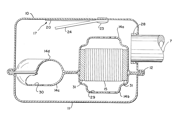
Referring now to Figs. 2 and 3, there is
iIlustrated in more detail mufflerassembly 2. Muffler
assembly 2 includes an exhaust tube 7 connected at one
end by means of an integral flange 8 to the exhaust
outlet from the cylinder head (not shown) of engine 1.
The opposite end of tube 7 is connected to a muffler 9
which is comprised of a two-piece hollow housing
including a cup-shaped body 10 and cover 11 which are
secured together by means of a circumferential clinch or
crimp 12. A bracket 13 is utili2ed to mount muffler 9
to the engine block. Muffler 9 includes a series of
perforated metal walls 14a, 14b and 14c and a solid wall
14d opposite wall 14c that form two separate chambers 29
and 30 for sound attenuation purposes. As shown best in
Fig. 3, a collar 28 projecting into the interior of body
10 is employed for guiding and attaching tube 7 to
muffler 9.
As shown best in Figs. 2 and 3, a catalytic
converter lS is mounted in chamber 29 within muffler~9
downstream of the inlet of tube 7 into the interior of
muffler 9 but upstream from the outlet 16 of muffler 9.
Converter lS is surrounded by a packing material 31
which functions as a temperature insulating and
vibration isolating means. All exhaust gas entering the
interior of muffler 9 first passes downwardly through
wall 14a into the first chamber 29 containing converter


~3~

_ 5 ~ 17~ ~

15 in order to oxidize components such as hydrocarbons,
carbon monoxide and nitrous oxide. In order to
accomplish this, catalytic converter 15 is in the form
of a honeycombed ceramic structure. The structure is
appropriately sized for the engine displacement and
emission reduction desired, and as illustrated in Fig. 2
is dimensioned approximately 3 inches by 1 inch by 1
inch for the 5 horsepower engine 1 illustrated in Fig.
1. The ceramic structure is coated with an oxidizing
and reducing catalyzer of any known composition.
Preferably, a combination of platinum, palladium an
rhodium is utilized. However, any combination of known
oxidizing and reducing catalyzer material may be
employed. After passing through converter 15, the
exhaust gas exits the first chamber 29 through wall
14b, then enters the second chamber 30 through wall 14c,
and finally exits muffler 9 through outlet 16.
As is well known in the art, in order to further
oxidize unburned exhaust gas components such as
hydrocarbons, carbon monoxide and nitrogen oxides in a
catalytic converter, there must be supplied additional
air to the catalytic converter. In order to accomplish
this, Figs. 4-5 illustrate a reed valve assembly
generally designated by the numeral 17. Reed valve
assembly 17 includes a pair of feed openings 18 and 19
formed through body 10 of muffler 9 so that the interior
of muffler 9 communicates with atmosphere. As shown
best in Fig. 4, openings 18 and 19 are substantially
oblong in shape and disposed parallel and adjacent to
one another. However, other specific arrangements may
be employed such as a single opening as opposed to two
openings, and the specific locations and dimensions for
these openings may be modified from that which is
illustrated in Fig.4. Reed valve assembly 17 also
includes a reed valve 20 having a pair of tongue members
21 and 22 cooperating with air openings 18 and 19

~77153
- 6 --

respectively. Reed valve 20 is comprised of thin
elastic tempered metal or the like and is fastened at
one end by a pair of rivets 23 to the inside surface of
body 10. A stop 24 in the form of a thin metal plate is
also mounted via rivets 23 to body 10 and as shown in
Fig. 5 is angled slightly away from the interior wall of
body 10. Stop 24 functions to prevent excessive flexing
of reed valve 20, as will hereinafter be described.
Fig. 6 illustrates a graph of muffler pressure over
time as determined by the crankshaft angle of engine 1.
Dashed line 25 in Fig. 6 is representative of
atmospheric pressure, namely, 14.7 pounds per square
inch. Peak 26 is representative of the opening of the
exhaust valve (not shown) in engine 1. Finally, peaks
such as those illustrated at 27 are representative of a
negative pressure in muffler 9 since these peaks are
below atmospheric pressure line 25. As a result, the
areas illustrated below line 25 in Fig. 6 will cause
reed valve 20 to open as they are representative of
negative pressure in muffler 9 whereas areas above line
25 in Fig. 6 will result in the closing of reed valve 20
as these are representative of pressures above
atmospheric. Thus, when closed, reed valve 20 prevents
exhaust leaks from muffler 9.
In operation, reed valve 20 is flexed or opened to
unseal air openings 18 and 19 during those times when
the pressure within muffler 9 is below atmospheric i.e.
below line 25 in Fig. 6. During these times, secondary
air from the atmosphere passes through air openings 18
and 19 into the interior of muffler 9 to aid in the
oxidation of exhaust gas components such as carbon
monoxide, oxides of nitrogen and various other
hydrocarbons prior to their discharge from outlet 16.
On the other hand, reed valve 20 is closed thus sealing
openings 18 and 19 to prevent exhaust leaks from muffler
9 whenever the pressure within muffler 9 is above line

207~1 ~3
_ - 7

25 in Flg. 6. Thus, reed valve 20 is ln a constant
state of movement to permit secondary air into muffler 9
at various times during one complete rotation of the
crankshaft of engine 1. There is thus provided a simple
and economical combination muffler/catalytic converter
structure and means for supplying secondary air to
catalytic converter 15.

Dessin représentatif
Une figure unique qui représente un dessin illustrant l'invention.
États administratifs

Pour une meilleure compréhension de l'état de la demande ou brevet qui figure sur cette page, la rubrique Mise en garde , et les descriptions de Brevet , États administratifs , Taxes périodiques et Historique des paiements devraient être consultées.

États administratifs

Titre Date
Date de délivrance prévu 1995-08-15
(22) Dépôt 1992-08-28
(41) Mise à la disponibilité du public 1993-03-01
Requête d'examen 1994-08-10
(45) Délivré 1995-08-15
Réputé périmé 2001-08-28

Historique d'abandonnement

Il n'y a pas d'historique d'abandonnement

Historique des paiements

Type de taxes Anniversaire Échéance Montant payé Date payée
Le dépôt d'une demande de brevet 0,00 $ 1992-08-28
Enregistrement de documents 0,00 $ 1993-03-23
Taxe de maintien en état - Demande - nouvelle loi 2 1994-08-29 100,00 $ 1994-07-13
Taxe de maintien en état - Demande - nouvelle loi 3 1995-08-28 100,00 $ 1995-07-20
Taxe de maintien en état - brevet - nouvelle loi 4 1996-08-28 100,00 $ 1996-07-19
Taxe de maintien en état - brevet - nouvelle loi 5 1997-08-28 150,00 $ 1997-07-24
Taxe de maintien en état - brevet - nouvelle loi 6 1998-08-28 150,00 $ 1998-07-30
Taxe de maintien en état - brevet - nouvelle loi 7 1999-08-30 150,00 $ 1999-07-21
Titulaires au dossier

Les titulaires actuels et antérieures au dossier sont affichés en ordre alphabétique.

Titulaires actuels au dossier
BRIGGS & STRATTON CORPORATION
Titulaires antérieures au dossier
WINBERG, JAMES R.
Les propriétaires antérieurs qui ne figurent pas dans la liste des « Propriétaires au dossier » apparaîtront dans d'autres documents au dossier.
Documents

Pour visionner les fichiers sélectionnés, entrer le code reCAPTCHA :


Pour visualiser une image, cliquer sur un lien dans la colonne description du document. Pour télécharger l'image (les images), cliquer l'une ou plusieurs cases à cocher dans la première colonne et ensuite cliquer sur le bouton "Télécharger sélection en format PDF (archive Zip)" ou le bouton "Télécharger sélection (en un fichier PDF fusionné)".

Liste des documents de brevet publiés et non publiés sur la BDBC .

Si vous avez des difficultés à accéder au contenu, veuillez communiquer avec le Centre de services à la clientèle au 1-866-997-1936, ou envoyer un courriel au Centre de service à la clientèle de l'OPIC.


Description du
Document 
Date
(yyyy-mm-dd) 
Nombre de pages   Taille de l'image (Ko) 
Abrégé 1995-08-15 1 31
Page couverture 1995-08-15 1 16
Abrégé 1995-08-15 1 31
Description 1995-08-15 7 292
Revendications 1995-08-15 4 179
Dessins 1995-08-15 3 77
Dessins représentatifs 1998-11-03 1 23
Correspondance reliée au PCT 1995-06-08 1 33
Lettre du bureau 1994-09-13 1 57
Correspondance de la poursuite 1994-08-10 1 32
Correspondance de la poursuite 1995-01-25 6 169
Demande d'examen 1994-09-26 1 46
Taxes 1996-07-19 1 71
Taxes 1995-07-20 1 73
Taxes 1994-07-13 1 70