Note : Les descriptions sont présentées dans la langue officielle dans laquelle elles ont été soumises.
CA 02077783 2001-12-10
BOAT TRANSPORTING AND LAUNCHING TRAILER
BACKGROUND OF THE INVENTION
1. Field:
The invention relates to boat trailers in general
and more particularly r_o boat trailers which facilitate
the launch and loading of boats into and from a body of
water at an inclined launching ramp.
2. State of the Art:
Prior art boat trailers are typically rigid,
unitary, structures, which, to launch the boat, are
backed into a body of water down an incline until the
boat floats free of side restraints, which have sun}: into
the water along with the trailer. Precariously
unrestrained, the boat may be buffeted by waves and wind,
and perhaps damaged even before it is detached from the
trailer. Boat recovery and loading is subject to the
same difficulties and dangers. The prior art reveals few
devices to improve boat trailers to facilitate water
launching and loading. Many are directed to raising and
lowering the boat carrying platform on level, dry,
ground, to aid in loading and unloading heavy objects for
transport overland. U.S. Patent Nos. 2,754,129 and
2,621,942, e.g. U.S. Patent No. 3,663,040 discloses a
similar trailer for transporting boats from point to
point within a boat fabrication, display, and sales yard.
None of these devices are suited for use with boat
launching and loading by way of inclined ramps, doing
nothing to control the direction or attitude of the boat.
The device disclosed in U.S. Patent No. 3,494,630 permits
the boat to be launched closer to the shoreline, by
lowering the boat platform upon the associated wheel
carriage. The device disclosed in U.S. Patent No.
4,529,217 provides some directional control of a boat
during loading. A pair of outrigger arms at the rear of
the trailer diverge when freed of the weight of the boat
in deep water, and return to vertical to center the boat
when withdrawn from the water. However, this device does
-1-
CA 02077783 2001-12-10
nothing to aid control of the boat during launch. U.S.
Patent No. 4,395,185 discloses two embodiments for
maintaining a level atr_itude of the boat-carrying portion
of the trailer when backed down a launching incline.
Each embodiment carries a pair of flotation units at the
rear of the boat-carrying portion and both involve
complex linkages and multiple pivots acting between the
boat-carrying portion and the remainder of the trailer.
The need therefore remains for an improved boat
trailer for launching and loading boats from bodies of
water at inclined ramps in the presence of buffeting wind
and wave.
_2_
CA 02077783 2001-O1-17
I~RZrr surarmr:~ or wuL lravrr;'rzoo
'r7itli the foregoing fu mind, the pzeseut invention
eliminates or substantially alleviates the shortcomings
and disadvantages of prior art trailers for transporting,
launching and loading boats into and out of tl~e water, by
providing such a trailer with a tongue-equipped, elongate,
rigid, lo~aer frame having a cradle upon which tlm boat is
carried. r~~ elongate, rigid, upper frame is pivotally
associated with tl~e lower frame, and has upstanding, hull-
engaging, side rails and attached flotation units which
maintain the frame and the rails at boat-retaining ele-
vation for launch and recovery from the water. Preferably,
a number of quickly attached and detached foot platforms
are provided, selectively positionable.upon t1e tongue and
the upper frame side members.
'i'lie frames each comprise a pair of elongate, spaced
apart, side members joined by cross braces generally bowed
down to clear the boat hull. 'fhe upper frame side members
rest upon the lower frame side members, h cross hinge joins
the frames at the bow end of the upper frame. 1~ pair of
stabilizing, two member, pivoting linkages connect the frames
rearwardly of the hinge.
when the trailer is bac);ed rearwardly down a typical
inclined boat-launching ramp into a body of water, the flo-
tation devices rotate t1e upper frame about the ~''~~no°. ~a'~s'n~
the frame stern end from the lower frame, so that it floats
generall,.~ level in tl~e water, with its side rails standing
~.~ertically, restraining the now floating boat. Preferably,
a hull contacting roller unit is provided on the rearmost
cross bore of the upper frame, to prevent hull scraping from
deeper draft boats not fioatiug completely clear, as well as
from wave-i«duced bobbing of boat or upper frame.'
CA 02077783 2001-12-10
During boat loading, the trailer is similarly
placed, the side rails guiding the boat into position in
the water above the boas cradle carried on the lower
frame. The boat and the upper frame then settle upon the
lower frame into J.and transport position when the trailer
is withdrawn up the ramp from the water.
An upstanding stanchion is, preferably, provided on
the forward end of the upper frame, with a clamp with a
pair of spring biased jaws to grip the towing ring on the
prow of the boat. A prow-engaging shock absorbing
device may also be employed to initially slow the boat
during loading.
Preferably, the tongue comprises an elongate member
slideably associated with the dower frame, which is
selectively extendable, so that the towing vehicle need
not back into the water at gradually sloping ramp sites.
It is therefore the principal object of the
invention to provide an improved boat trailer,
facilitating launching and loading at inclined launch
ramps, by maintaining positive control over the boat
during both operations.
-4-
CA 02077783 2001-12-10
DETAILED DESCRIPTION OF
ILLUSTRATED EMBODIMENTS
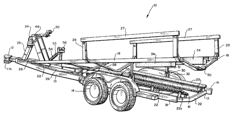
Referring now to r_he figures in general and to FIG.
1 in particular, there is depicted a perspective view of
an embodiment of the boat transporting and launching
trailer 10 of the present invention.
Trailer 10, coupled to hitch llh of a towing vehicle
11 by a tongue assembly 12, comprises a lower rigid frame
assembly 13, mounted upon a wheeled undercarriage 14 and
supporting a boat platform 15 comprised of hull
contacting elongate slats 16. An upper rigid frame
assembly 17 has a pair of elongate side members 18, which
during the road transport mode of operation of trailer 10
rest (FIG. 2) upon a pair of elongate side members 19 of
lower frame 13, to which the foremost end 21 of upper
frame 17 is secured by cross hinge assembly 20. (FIGS.
2-4) In FIG. 1, upper frame 17 is shown pivotally raised
above lower frame 13, for clarity of illustration.
Lower frame 13 comprises the two elongate side
members 19, formed to generally come together in an apex
at tongue assembly 12. Welded cross braces 22 assure
rigidity of lower frame 13, and carry upstanding, welded,
supports 22s for the slats 16 of boat cradle platform 15.
To position the boat upon trailer 10, side rails 27 are
proved upon welded supports 29 upstanding from elongate
side members 18 of upper frame 1'7. Welded cross braces
22 assure the rigidity of upper frame 17.
A boat loading and launching winch 24 may be
provided forwardly of hinge 20, with an upstanding
support post 25 secured to lower frame 13, as to a
tongue-housing beam 26. Winch 24 could be relied upon to
secure the boat upon trailer 10. Preferably, however a
hitching assembly 46 is provided upstanding from the
stern end of upper frame 17. Spring loaded jaws 47 clamp
and retain towing ring 48 on boat prow 49, which is
secured undamaged by operation of a pair of rubberoid
--6-
CA 02077783 2001-12-10
buffer wheels 50. Winch line 51 may, as a safety
precaution, also be hooked to ring 48. (FIGS. 1-3, 8)
Instead of relying entirely upon buffer wheels 50, a
shock absorbing structure 53 may also be provided. (FIG.
1) Compression spring 54 is pivotally attached at its
forward end to upper frame 17, and at its other end to a
pivoting arm 55 upstanding from frame 17. Arm 55 carries
another pair of prow-contacting rubberoid wheels 56.
With shock absorber 53, the boat may be powered rapidly
into position without danger of hull or prow damage.
A pair of linkages 30, each with an upper and a
lower pivoting member 31 and 32, act with cross hinge 20
to stabilize upper frame 17 when it is in raised position
during launch and loading modes. The cross braces 22 and
28 of lower and upper frames respectively all bow
downwardly between respective side members 19 and 18 to
provide bottom clearance for the boat hull, supported
upon the cradle members 23. To allow upper frame 17 to
be raised an lowered from lower frame 13, the longer pair
of cradle members 16 is constructed with clearance gap 33
for one of the upper frame cross braces 28.
A pair of flotation devices 34, secured to the stern
ends of side frame members 18, maintains upper frame 17
in a level position during boat launching and loading, as
explained in detail below. Floats 34 may be comprised of
a mass of buoyant material, or of wall members sealed
together to define a void space. The floats 34 are
preferably sized to impart a slight positive buoyancy to
the stern end of upper frame 17.
Referring now to FTG. 2, there is depicted a side
view of a boat-laden trailer 10 in pre-launch position
upon a launch ramp 35, in preparation for vehicle 11 to
back it into the water, in the manner well known in the
art.
In Fig. 3 there is shown a boat trailer 10 in the
post-launch, pre-recovery, position, the boat floating
upon the water preparatory for loading. Trailer 10 has
_7_
CA 02077783 2001-12-10
been backed into the water down ramp 35. As the depth of
the water increases, the resultant buoyancy upon the boat
causes it to float, and floats 34 cause upper frame 17
with boat restraining side rails 27 to also float,
pivoting about hinge 20, stabilized by the pair of
linkages 30. In floated position, the stern ends of side
members 18, and the tops of the flotation units 34, are
generally at the surface of. the water.
The boat is released from winch line 51 and jaws 47,
and launched from betwE>.en rails 27, either manually or
under its own power. Some boats may have sufficient
draft as to not float entirely free of upper frame 17.
In this event roller 52, mounted upon the rearmost of the
cross braces 28, prevents any damage consequent to hull
scraping. (FIG. 1)
When being loaded, the boat may, if desired, be
pulled manually, or by winch 24, between, and guided by,
rails 27. Preferably, the boat is driven, under its own
power, onto upper frame 17, guided as necessary by rails
27. Prow 49 first impacts shock absorber wheels 56, and
then nudges buffer wheels 50 as towing ring 48 is engaged
by spring-loaded jaws 47. Roller 52 prevents any
scraping of the bottom of the hull against frame 17.
With the boat in loaded position, trailer 10 may be drawn
from the water up the ramp 35, the boat and upper frame
17 settling together into road transport position when
emerging from the water.
The boat floats safely above trailer cradle 15
during both launch and recovery. During recovery, guide
rails 27 ensure that the boat is properly positioned
above support cradle 15, especially important when strong
winds and waves are present.
To facilitate any manual guidance of the boat which
may be needed during launch or recovery, step units 36
are employed, principally upon upper frame side members
18, and, when needed, upon tongue member 39 and portions
of lower frame side members 19. Foot platform members
-8-
CA 02077783 2001-12-10
37, channel shaped for rigidity, for example, carry
welded-on angles 38, spaced apart as necessary to embrace
tongue or frame side members. Non-slip treads, not
shown, may be employed upon the cantilevered foot
platforms 37.
With state-of-the-art boat trailers, the towing
vehicle must often itself be backed into the water to
obtain sufficient water depth to float the boat for
launch. Trailer 10, however, incorporates an extensible
elongate tongue member 39 telescoped inside a box beam
housing 40 running from the front end of frame 13
rearwardly under and past hinge 20. Longitudinal slot 41
in the bottom member of housing 40 accepts a guide pin 42
welded downstanding from the rearmost end of tongue 39.
Spaced apart positioning holes 43, bored vertically
through tongue 39, allow it to be secured to project a
selective distance, using an indexing pin 45. An
indexing hole 44 is provided through housing 40. (FIG.
5) The vehicle connection end of tongue 39 is provided
with state-of-the-art connection means, such as a socket
to accept a vehicle mounted hitching ball along with
conventional safety chains and the like, not shown.
Trailer 10 also incorporates rear signal lights, along
with wiring and control cables communicating with the
towing vehicle, neither being shown.
The invention may be embodied in other specific
forms without departing from the spirit or essential
characteristics thereof. The present embodiments are
therefore to be considered as illustrative and not
restrictive, the scope of the invention being indicated
by the appended r_laims rather than by the foregoing
description, and all changes that come within the meaning
and range of equivalency of the claims are therefore
intended to be embraced therein.
_g_