Note : Les descriptions sont présentées dans la langue officielle dans laquelle elles ont été soumises.
a6 ~.''~~~ ;~
This invention relates to coated abrasive shapes
and the method of making such shapes for use at speeds of
the order of 10,000 - 1S,000 RPM for use on machines such
as heavy grinding machines and the like. The shapes with
which the invention is concerned are provided with a
aperture for mechanical mounting on a base surface.
The abrasive product made in accord with this in-
vention is a suitable backing material available in sheet
form with cured adhesive thereon, and abrasive particles
embedded in such adhesive.
Because of the speed (of the order of I0,000 - 15,000
RPM) at which such grinding machines operate, the backing
material has had to be made of material greater than .010'~
(ten thousandths of an inch) in thickness and preferably of
material of the order of .025" - .040" (twenty-five to forty
thousandths of an inch). Backing materials may include the
chocolate olive vulcanized abrasive fibre mentioned in the
preferred embodiment, laminated fibre sheets, plastic alloy
materials, laminated paper and other suitable backing materials
all of the required thickness.
Thus, the 'shapes' referred to herein are two
dimensional outlines of the backing material with abrasive-
containing coating on one side or may be coated on both sides.
A large proportion of the shapes made in accord with
the invention will be circular discs (plus connecting material
as hereinafter explained) for use on rotary tools and grinders.
~'fhe disks may be octagonal or hexagonal. The disks will have a
central aperture for mounting.
... ~'~~~ ~J 1~ S, y1.
(usually by a nut screwed on a bolt extending through the
centre aperture). However, the shapes may be other than
circular as noted herein.
The older prior art method of making circular shaped
coated abrasive products on a backing sheet was to apply the
adhesive binder and the abrasive grit to one side of a wide
roll of backing material such as paper, cloth, plastic or
fibre, etc. After the coating, drying and curing processes,
the finished roll is placed in a punch press cutting machine
and the discs or shapes are stamped out, leaving a lattice
work of perfectly good coated abrasive material as waste that
must be disposed of environmentally. The 'punching out' or
cutting of shapes from coated abrasive products also creates
an extreme amount of wear and tear on the punching and cutting
machinery.
A newer prior art method was developed to overcome
the two major disadvantages of the older method described above.
This newer method involved cutting the desired praduct shaped
in the backing material in advance of the adhesive and grit
to form the finished product. This newer prior art method not
only avoided the wear and tear on the punching or cutting
machinery, but also virtually eliminates the adhesive and
abrasive material that is wasted, as noted, when using the
other method.
-2-
CA 02080329 1998-07-14
Disadvantages of the newer prior art method are the expense and
time delay in handling the individual backing and product shapes during the
coating, curing and
subsequent manufacturing or finishing steps. Although the following example
does not express
the full extent of this problem, it is noted that for example, equal handling
time is required to
handle a small diameter four inch disc, as a larger diameter nine inch disc,
and the individual
handling of both is inconvenient and time consuming.
U.S. Patents 3,267,623 of 8/23/66 and 3,849,949 of l1/26/84
disclose connected abrasive-coated disks for detachment and individual use.
However such disks
are in practice directed to light grinding or finishing operation at about 500
RPM and because such
are the uses, the thickness of the backing materials is about .003" being
attached to sanding pads
by a pressure sensitive adhesive. In contrast the disks or abrasive shapes
with which applicant
is concerned are used for heavy grinding at speeds of the order of 10,000 -
15,000 RPM and the
backing material is greater than .0l0" in thickness and preferably about .025"
- .040" thick and
being attached to grinders by mechanical means.
The patents 3,267,623 and 3,849,949 refer to a method of production
which involves material, already coated with abrasive, and any other coatings
required before
being cut into connected disks and before the provision of any weakened
detaching lines. By
contrast, in applicant's method, the backing material is first cut into
connected disks or other
shapes, before being provided with abrasive and/or other coatings. This if for
the reasons
discussed in paragraph 6 of
-3-
~;~'~~~''' '
this application. Moreover the 'nicking' or weakening of the
backing material is, in applicant's method, also performed
before the coating step so that wear on the operating
machinery is, lessened. It is~ found that without this weakening
at the connection point~the disks, after coating with abrasive
and curing~will not break apart cleanly.
Accordingly, in accord with this invention, our
novel method comprises stamping out from an uncoated backing
sh ee t a first plurality of apertured shapes interconnected at suitable
locations so that they are arranged in an orderly pattern or
array during the coating steps. The percentage of the periphery
of the backing material shape having connecting material to
another shape is less than 10%, preferably less than S% and
ideally about 1% - 2%. Tf cuts or nicks or other means are
used to weaken the backing material between adjacent disks
then such cuts, nicks or other weakening a~ performed by
appropriate machinery just after the stamping out of the shapes
or simultaneously therewith. This first plurality of connected
shapes (or a second plurality forming a sub-group of the first)
is then coated with abrasive embedded in adhesive, cured and
subjected to the normal finishing processes. Thus the connected
arrangement of a number of shapes may be maintained through a11
the coating and processing steps, and in fact a number of the
shapes may still be attached when the product is sold to the
customer) The reason for having a first plurality and a second
which may be a sub-group of the first is to cover the possibility
-4-
~~''r.~
that it may be desirable to stamp out the backing material
in a large two dimensional array--for examples: rows and
columns of members: or a hexagonal arrangement of circular
discs, in either case being -the first plurality: then per-
forming the remaining process steps on a smaller array
detached from the first, say a single row of connected shapes.
The process as described in the previous paragraph
has the advantage that the loss of abrasive and adhesive is
negligible since a large percentage of the coated material
forms a usable part of the finished individual (shape). On
the other hand, the handling and processing time is saved
since a group of connected shapes are processed together.
In each step from the coating to the final packaging and ship-
ping for use, handling and processing time is saved if the
shapes remain attached. The novel process also shares with
the newer prior method the advantage that, since the backing
material is stamped or cut while uncoated, wear and tear on
the corresponding cutter or punch press is avoided.
It is therefore an object of this invention to
_provide an abrasive coated product comprising the steps of:
stamping backing material to form a first plurality of inter-
connected shapes corresponding to those for finished abrasive
products, where the proportion of the periphery of each shape
having connecting material to other shapes is less than 10%
' and taking such plurality or a connected sub-group thereof
through the necessary process steps to provide a coated backing
-5-
,n ay
~~'~-~<~:t,.'~J
with abrasive grit embedded therein and subsequently con-
verting these pluralities of connected shapes into finished
abrasive disc like products.
'tt is an object of~a preferred facet of the invention
to provide the process above-described wherein the connected
shapes have a periphery at the connecting point area of less
than 10% and preferably about 1% to 2% that is relatively flat
as opposed to the curvature of the shape.
It is an object of a preferred facet of the in-
vention to provide the process first described where the
circular shapes are connected along mutually orthogonal lines.
This provides for greatly simplified separation of an array
of shapes into rows or into individual shapes.
It is an object of a preferred facet of the in-
vention to provide the process first described where the
uncoated backing cut into connected shapes is provided with
weakened lines for separation at the connection as required
for finished coated abrasive products.
So far as saving of backing material, abrasive material
and adhesive, the proportion of the periphery of a shape which
connects to each adjacent shape in an array will be as small
as possible. The lower limit for such proportion will be set
by the fact that there must be sufficient connecting material
to avoid breakage between connected shapes of backing without
or with abrasive coati~;g during and after the manufacturing
-6-
2~'~:~'~''' ~
process. For example with a 4 inch diameter disc, we have
found that only a 1/8" extent of periphery (about 1% of the
circumference) is reguired for connection to any adjacent
disc. However, it will be.noted that for a 9 inch disc,
although the periphery has approximately doubled, the area
(and hence the weight of backing or abrasive) has increased by
a factor of 5. Thus the proportion of the periphery used for
connection may have to be higher with a larger disc and will
be affected by the weight of abrasive used. However, for
basically circular shapes the proportion can be less than 10%.
It is an object of the invention to provide products
resulting from the processes of the foregoing three paragraphs.
In drawings which illustrate a preferred embodiment
of the invention:
Figure 1 shows a rectilinear array of connected
circular or disc shapes in accord with the invention,
Figure 2 shows an array of connected octagonal
shapes in accord with the invention,
Figure 3 shows a hexagonal array of circular shapes,
Figure G. shows a section along the lines 4 - 4 of
Figure 1,
~ ~d~t~,"/~'-~Q
~~~K.W e.:tJ
Figure 5 shows a production line in accord with
the invention,
Figure 5A shows a perspective of a portion of the
line of Figure 5.
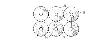
In drawings Figure 1 shows as preferred form of
the interconnected shapes. A web of backing was used to stamp
out a connected arrangement of 6 circular discs 12 in a 3 x
2 rectilinear array. The stamping process included the
simultaneous stamping of centre apertures 11 for receiving the
shank of a mounting bolt so that the shapes may be mounted by
a nut tightened onto the bolt. The array may be of any size.
The circular shapes are spaced just wider than the spacing
for co-tangency and at each connection of one disc to a single
other disc, the connecting blank material is left to connect
1-2% of the disc circumference. The discs are customarily
provided 4" with a 5/8" centre hole 11.
The backing material is greater than .010 inches
thick and is preferably chocolate-olive abrasive fibre thick-
ness of .030 inches which is available from National Vulcanized
Fibre Company of Yorklyn Delaware. Any suitable backing material
may however be used. The connected shapes are customarily
made from the backing material in a punch press cutting machine.
It will be noted that the connected shapes are arranged so
that they may be separated along mutually orthogonal lines.
The scope of the invention is however independent
-g-
~~~ ~i ~~t.:1'r~W
of the connected shape which may be of any form for which
coated abrasive on a backing is required.
After the stamping of one of the shapes shown in
Figures 1, 2 or 3; or different shapes or a different array,
the array may be subject to a second cutting process in a
punch press wherein each line corresponding to the junction
of the thickness, leaving 1/3 of the thickness still intact
and joined as shown in Figure 4. The second cutting operation
if required is designed to weaken the connection between the
shapes for later separation.
Thus the second cutting operation may be replaced
by any other conventional method such as scoring or perforating
for weakening the separation line 14 for future separation.
In an alternative to the second cutting operation, it may be
preferred to use a single pass operation where the stamping
out of connected shapes is combined with the partial cutting
of the connecting lines.
However it is found that unless the connection between
shapes is weakened before the backing material is coated and
covered with adhesive the shapes and disks do not break apart
'cleanly.
Also it should be noted that the array after the
second cutting operation may be a different shape from that
processed in the further steps to be described. Thus for
example, it might be desired to form 36 discs in a 6 x 6 rect-
ilinear array in the first and second cutting operation and then
separate such strips into six rows of six (or into
_g_
~' ~a''i..8'~L.~:Y, .:a
a 3x2 array) for further processing. With the materials shown, we have
found that such separation may be performed by a 45~ bending operation
'pe:-fo~"ed by any conventional means,
6~Jhere the shapes are polygons, as vJith the octagon
of Figure 2 the separation line l4 may be formed of complete cuts
C at each end with a very narrow connecting tab T.
The connected unit being an array of the first
plurality of shapes or sub-array of a smaller second plurality
of shapes, as selected, is then subjected to the conventional
processing steps as shoran in Figures 5 and 5A. The array or
sub-array 15 or a group of them are passed through a con-
ventional spray Line adhesive coater 16, after which it is
subjected to a conventional electrostatic application of
abrasive grain at applicator 18. The arrays 15 are then
subjected to a conventional drying process in dryer 20,
followed by a second coating of adhesive in a conventional
spray line adhesive coater 22 followed by a high temperature
cure in oven 24 to complete the manufacturing cycle.
It will be noted that all the steps of the manu-
facturing process are conventional and performed by con-
ventional equipment. However, it also should be noted that
the spray line adhesive coaters 16 or 22 recover the adhesive
which does not come to rest on the backing. It is for this
reason that savings are achieved with the inventive connected
array since substantially all adhesive which misses the array
is reclaimed below the coating area for re-use. Similar
considerations apply to the electrostatic applicator 18.
Abrasive grit from the applicator 18 which does not come to
-10-
~'' ~:~~v''',~
rest on the adhesive, falls into a recovery area for re-u'se.
Any conventional method for applying the abrasive
carrying adhesive will be within the scope of the invention.
However, only those methods which allow reclamation of
adhesive and grit which is dispensed but not used will achieve
the full advantages of the invention in this area. However,
even without such reclamation, the labor saving aspects of
the invention involved in easier handling of the arrays or
sub-arrays still apply.
The manufactured unit from oven 24 is then con-
ventionally placed in a humidity chamber to condition and
normalize the product and this step is customarily followed
by passing the unit between a rubber and steel pressure roll
and finally through a printing machine to mark the back side
of the product with pertinent information.
The unit may then be separated into individual
abrasive units or into connected sub-groups for sale. With
the second cut shown in Figure 4, we have found that a 45~
bend will separate the shapes along any of the separation
lines.
It will have been noted that products of the inventive
process.have small amounts of connecting material.
-11-
'~,4''' ~'.. ~ ~~ ' <~.
t. ,_, J e.u;
(extending to line 14) about small extents of the desired
shape. This has not been found to interfere with the operation
of the product, whether rotating or non rotating.
-12-