Note : Les descriptions sont présentées dans la langue officielle dans laquelle elles ont été soumises.
2 0 ~
--1--
CATALYTIC ELEMENT FO~ MARINE PROPULSIO~ DEVIC~
BACKGROU~D OF THE INVENTION
The invention relates generally to marine propulsion devices
such as outboard motors and stern drive units. More particularly,
the invention relates to catalytic elements in exhaust gas
passageways in marine propulsion devices.
SUMMARY OF THE INVENTION
The invention provides a marine propulsion device comprising
a propulsion unit including a propeller shaft, a housing including
an exhaust gas inlet and an exhaust gas outlet, a catalytic element
housed in the housing for reorientation from a first orientation to
a second orientation different from the first orientation, and
means for reorienting the element from the first orientation to the
second orientation.
One embodiment of the invention provides a marine propulsion
device comprising a propulsion unit including a propeller shaft,
and a housing defining an exhaust gas passageway, the exhaust gas
passageway having therein a shoulder, the marine propulsion device
further comprising a catalytic element, including a rib, in the
exhaust gas passageway, and a retaining sleeve which is mounted in
the housing and which partially surrounds the element such that the
rib is captured between the shoulder and the retaining sleeve.
~ -2- 2~83~26
One embodiment of the invention provides a method of
maintaining a catalytic element in an engine apparatus including a
housing defining an exhaust gas passageway, the method comprising
the steps of providing the element in a first orientation in the
exhaust gas passageway, and reorienting the element from the first
orientation to a second orientation different from the first
orientation.
One embodiment of the invention provides a method of
maintaining a catalytic element in a marine propulsion device
comprising a propulsion unit including an exhaust gas passageway
and a propeller shaft, the method comprising the steps of providing
the element in a first orientation in the exhaust gas passageway,
and reorienting the element from the first orientation to a second
orientation different from the first orientation.
The inventors of the present invention have found that in
marine propulsion devices comprising an internal combustion engine,
an exhaust passageway having an exhaust gas inlet and an exhaust
gas outlet, and a catalytic element (catalyst) in the exhaust
passageway, deposits accumulate on a side of the catalytic element
facing the exhaust gas inlet. These deposits are from impurities
in fuel and oil combusted by the internal combustion engine (some
marine propulsion devices include two stroke engines which require
a fuel including mixing oil mixed with gasoline), engine wear
particles, salt from sea water ingested by the engine, and the
like. In addition to these deposits, when the engine is operated
with a light load, a layer of carbonaceous material can build up on
the side of the catalytic element facing the exhaust gas inlet.
-3~ 2~$3'~
Some of this carbonaceous material remains even after subsequent
operation of the engine at higher loads.
The inventors of the present invention have also found that
after some carbonaceous material and some deposits have built up on
one side of the catalytic element facing the exhaust gas inlet, if
the element is reoriented so that this side now faces the exhaust
gas outlet, at least some of the deposits and carbonaceous material
will be blown off of the catalytic element by exhaust gas passing
through the catalytic element. Thus, the useful life of the
catalytic element is extended.
Other features and advantages of the invention will become
apparent to those of ordinary skill in the art upon review of the
following detailed description, claims, and drawings.
DESCRIPTION OF TH~ DRAWINGS
Fig. 1 is a side elevational view of a marine propulsion
device which includes a housing, and a catalytic element housed in
the housing, and which embodies various of the features of the
invention.
Fig. 2 is a broken away side elevational view of the marine
propulsion device, partly in section, and showing the catalytic
element not in section.
Fig. 3 is a broken away side elevational view of the marine
propulsion device, partly in section, and showing the catalytic
element in section.
Fig. 4 is an enlarged, broken away, sectional, side
elevational view of the marine propulsion device, showing the
"", ,,
catalytic element in section, and showing in detail how the
catalytic element is housed in the housinq.
Fig. 5 is a broken away, sectional, rear elevational view of
an alternative embodiment of the invention.
Fig. 6 is a view taken along line 6-6 in Fig. 5.
Fig. 7 is a broken away side elevational view of a second
alternative embodiment of the invention.
Fig. 8 is a view taken along line 8-8 in Fig. 7.
Before one embodiment of the invention is explained in detail,
it is to be understood that the invention is not limited in its
application to the details of construction and the arrangement of
components set forth in the following description or illustrated in
the drawings. The invention is capable of other embodiments and of
being practiced or carried out in various ways. Also, it is to be
understood that the phraseology and terminology used herein is for
the purpose of description and should not be regarded as limiting.
- ~5~ 2 ~ 7 ~
DETAILED DESCRIPTION OF THE
PREFERRED EMBODIME~T OF ~E INVENTION
A marine propulsion device 12 embodying the invention is
illustrated in Figs. 1-4. While the illustrated marine propulsion
device is an outboard motor, the invention is also applicable to
other types of marine propulsion devices such as stern drive units.
The marine propulsion device 12 comprises (see Fig. 1) a
transom bracket 14 fixedly mounted to a transom 16 of a boat, and
a swivel bracket 18 which is mounted on the transom bracket 14 for
pivotal movement relative thereto about a generally horizontally
extending tilt axis 20.
The marine propulsion device 12 also includes a propulsion
unit 22 which is connected to the swivel bracket 18 for common
movement therewith about the tilt axis 20 and for pivotal movement
relative to the swivel bracket 18 about a generally vertical
steering axis 24.
The propulsion unit 22 comprises a lower unit 26. The lower
unit 26 includes a propeller shaft 28 supporting a propeller 30, a
reversing transmission 32, and a driveshaft 34 drivingly connected
to the propeller shaft 28 via the reversing transmission 32. The
lower unit 26 further includes an exhaust gas discharge outlet 36
which, in the illustrated embodiment, is of a through-the-propeller
type. Alternative exhaust gas discharge outlet locations can also
be employed. The lower unit 26 has an upper end 38 and defines an
exhaust gas passageway 40 extending from the upper end 38 to the
discharge outlet 36.
-6- 20834~
The propulsion unit 22 further comprises a powerhead 42 bolted
or otherwise solidly connected to the upper end 38 of the lower
unit 26. The powerhead 42 includes an internal combustion engine
44 drivinqly connected to the driveshaft 34. The engine 44
includes an engine block 46 having therein cylinders 48. The lower
end of the engine block 46 has therein (see Fig. 3) an exhaust gas
outlet 50 communicating with the cylinder6 48. The powerhead 42
further comprises an adapter or housing 52 for facilitating
mounting of the engine block 46 to the lower unit 26, as is known
in the art. Optionally, the adapter 52 is omitted. The adapter 52
has an upper end 54 having therein an exhaust gas inlet 56
communicating with the exhaust gas outlet 50 in the engine block
46, and has a lower end 58 having therein an exhaust gas outlet 60
communicating with the exhaust gas passageway 40 in the lower unit
26, and the adapter defines an exhaust gas passageway 62 extending
between the exhaust gas inlet 56 and the exhaust gas outlet 60.
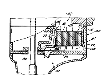
The exhaust gas passageway 62 is defined by (see Figs. 2-4) a
first inner cylindrical surface 64 having a first inner diameter,
and a second inner cylindrical surface 66 that is directly below
t~e first inner cylindrical surface 64, that has a second inner
diameter greater than the first inner diameter, and that is axially
aligned with and adjacent to the first inner cylindrical surface
64. A 6houlder 68 is defined between the first inner cylindrical
surface 64 and the second inner cylindrical surface 66. The second
inner cylindrical surface 66 has a therein a groove 70 for a
purpose that will later be explained.
~7~ 2 ~
The propulsion unit 22 further includes a generally
cylindrically shaped catalytic element 72 supported in the exhaust
gas passaqeway 62. In the illustrated embodiment, the element 72
is housed in the lower end 58 of the adapter 52 so that the element
72 is accessible for servicing when the powerhead 42 is separated
from the lower unit 26. If the adapter 52 is omitted, the element
72 can be housed in the lower end of the engine block 46 so that
the element 72 is still accessible for servicing when the powerhead
42 is separated from the lower unit 26.
The element 72 comprises catalyst material 74 surrounded by a
cylindrical sleeve 76. The sleeve 76 includes a rib 78 and the
element has first and second circular ends 80 and 82, respectively.
In the illustrated embodiment, the rib 78 extends circumferentially
around the sleeve 76 and is located halfway between the first and
second ends 80 and 82. The element 72 is selectively housed in the
exhaust gas passageway 62 in one of a first orientation, in which
the first end 80 of the element 72 faces the exhaust gas inlet 56,
and a second orientation, in which the second end 82 of the element
72 faces the exhaust gas inlet 56.
The propulsion unit 22 further includes a retaining sleeve 84,
generally in the shape of an open-ended hollow cylinder, having
(see Fig. 4) first and second (or upper and lower) ends 86 and 88,
respectively. The retaining sleeve 84 is removably mounted in the
exhau~t gas passageway 62 and partially surrounds the element 72
when the element 72 is housed in the exhaust gas passageway 62.
The retaining sleeve 84 has theron a flange 90 extending outwardly
from the lower end 88 thereof. When the catalytic element 72 is
2 ~ g ~
housed in the exhaust passageway 62 in the first orientation, or
the second orientation, the retaining sleeve 84 is mounted in the
exhaust gas passageway 62 such that the rib 78 i8 captured between
the shoulder 68 and the end 86 of the retaining sleeve 84.
The propulsion unit 22 further includes an outwardly biased
retaining ring 92 selectively received in the groove 70. The
retaining ring 92 abuts the flange 90 and thereby retains the
retaining sleeve 84 in the exhaust passageway when the element 72
is in the first orientation and when the element 72 is in the
second orientation.
The catalytic element 72 is maintained by being periodically
reoriented to extend the useful life of the catalyst material 74.
Assuming that the element 72 is initially in the first orientation
in the exhaust gas passageway 62, the element 72 is reoriented by
removing the retaining ring 92 from the exhaust gas passageway 62,
removing the retaining sleeve from the exhaust gas passageway 62,
removing the element 72 from the exhaust gas passageway 62,
reinserting the element 72 into the exhaust gas passageway 62 in
the second orientation, reinserting the retaining sleeve in the
exhaust gas passageway 62, and reinserting the retaining ring 92 in
the exhaust gas passageway 62. The element 72 is similarly
reoriented from the second orientation to the-first orientation.
A marine propulsion device 200 that is an alternative
embodiment of the invention is illustrated in Figs. 5 and 6.
Except as described below, the marine propulsion device 200 is
substantially identical to the marine propulsion device 12, like
reference numerals indicating like components. The marine
20~3~
propulsion device 200 comprises a propulsion unit 222 including an
exhaust gas manifold or housing 224 that i8 bolted or otherwise
fixedly attached to the engine block 46, and that defines an
exhaust gas passageway 240 communicating between the cylinder
exhaust ports 246 and the exhaust gas passageway 40 in the lower
unit 26.
The propulsion unit 222 includes a catalytic element 272
located in the exhaust gas passageway 240 and supported by the
exhaust gas manifold 224 for reorientation from a first orientation
to a second orientation, and includes means for reorienting the
element 272 from the first orientation to the second orientation
while the element 272 is in the exhaust gas passageway 240. More
particularly, in the illustrated embodiment, the reorienting means
comprise~ means exterior of the exhaust gas passageway 240. Still
more particularly, the element 272 is pivotally mounted in the
exhaust gas passageway 240, and the reorienting means pivots the
element 272 about a pivot axis 278. In the illustrated embodiment,
the element 272 is pivoted through 180, from the first orientation
to the second orientation, about the pivot axis 278. The
propulsion unit 222 further in~ludes a shaft 282 that is connected
to the element 272 and that has a portion exterior of the exhaust
ga~ manifold 224. While various other means could be employed, in
the illu~trated embodiment, the reorienting means comprises a crank
handle 286 connected to the shaft 282. The catalytic element 272
i5 reoriented by turning the crank handle 286 to pivot the element
272 through 180 from the first orientation to the second
orientation.
-lo- 2 ~
A marine propulsion device 300 that is a second alternative
embodiment of the invention is illustrated in Figs. 7 and 8.
Except as described below, the marine propulsion device 300 is
substantially identical to the marine propulsion device 12, like
reference numerals indicating like components. The marine
propulsion device 300 comprises a propulsion unit 322 including an
exhaust gas manifold or housing 324 that is bolted or otherwise
fixedly attached to the engine block 46, and that defines an
exhaust gas passageway 340 communicating between the cylinder
exhaust port(s) 396 and the exhaust gas passageway 40 in the lower
unit 26. The propulsion unit 322 includes a catalytic element 372
located in the exhaust gas passageway 340 and fixedly supported in
the exhaust gas manifold 324. The propulsion unit 322 further
includes first and second diverters 376 and 378, respectively,
pivotally mounted in the exhaust gas manifold 324. The propulsion
unit 322 further includes shafts 380 and 382 that are respectively
connected to the diverters 376 and 378, and that include portions
extending out of the exhaust gas manifold 324, and crank handles
384 and 386 respectively connected to the shafts 380 and 382
outside the manifold 324. The diverters 376 and 378 and the
exhaust gas manifold 324 cooperate to selectively define one of a
f~rst exhaust path (shown with solid arrows), such that exhaust gas
flow~ through the catalytic element in a first direction, and a
second exhaust path (shown with dashed arrows), such that exhaust
ga~ flows through the catalytic element in a second direction
oppo~ite to the first direction. The diverters 376 and 378 are
pivoted by a user, by means of the handles 384 and 386, from their
-11- 20~34~
positions shown in Fig. 7 in solid outline, to the positions shown
in dashed outline, to change the flow of the exhaust gas fro~ the
first direction to the second direction.
Various of the features of the invention are set forth in the
following claims.