Note : Les descriptions sont présentées dans la langue officielle dans laquelle elles ont été soumises.
1
HOT BLAST STOVE AND
ME'PHOD FOR CONSTRUCTING A HOT BLAS'P STOVE
BACKGROUND OF THE INVENTION
1. FIELD OF THE INVENTION
The invention relates to a hot blast stove
5 having a refractory structure of ~twa or more walls
consisting mainly of bricks, which walls are joined
together with joining elements connecting into 'them,
and to a method for constructing such a hot blast
stove.
2. DESCRIPTION OF THE PRIOR ART
Hot blast stoves are well known and are used
for heating the air blown into a blast furnace. One
known form of hot blast stove consists of a surrounding
wall within which there is a combustion shaft and a
checker work shaft, which shafts are separated by a
partition wall joined to the surrounding wall on both
sides by means of joining elements. In the case of
this known hot blast stove the bricks and the joining
elements are preformed, pressed and burned bricks.
These joining elements in the form of bricks frequently
have a complex shape and serve to provide the various
connections, for example between the surrounding wall
and the partition wall. Because the walls are erected
in a brickwork bond, the joining bricks also have
2
differing shapes for differing courses of which the
wall is composed. For constructing the known hot blast
stove the joining bricks are made in advance by
pressing them in specifically designed heavy press
moulds. The variation arising in shape of the
different joining bricks necessitates corresponding
variation of press moulds which causes considerable
costs. Figs. lA, 1B and 1C of the accompanying
drawings serve to illustrate that different joining
bricks are used in one hot blast stove; in practice -the
number is greater than 35, and so the same number of
differing press moulds are needed for making them. In
addition, the shaping possibilities and the shape of
the prefabricated joining bricks which have to be
fitted so that they link well into the brickwork limit
design and construction possibilities of the known hot
blast stove.
Constructions and brickwork of hot blast stoves
are illustrated in articles Stahl and Eisen Vol. 95
(1975) No. 17, pages 802-806 and Metallurgist, Vol 23,
no. 1/2 (1979), pages 97,98 .
SUMMARY OF THE INVENTION
The object of the invention is to provide a hot
blast stove and a method for its construction, in which
the drawbacks mentioned above are removed. In
particular the invention has the object of providing a
9
3
method by which the need for large numbers of heavy
press moulds is avoided.
According to the invention in its method
aspect, there is provided a method for constructing a
hot blast stove having two refractory walls joined to
each other at a joint, said method comprising building
'the two walls mainly of bricks and incorporating at
least one cast joining element at the joint of the
walls.
Preferably in a plurality of courses and/or
layers of the bricks of the walls, cast joining
elements are used at the wall joint. The cast joining
elements may be pre-formed before incorporation in the
walls, in which case they may be made in relatively
light and simple moulds and do not require baking.
Alternatively the cast joining element or elements are
cast in situ at their locations in the wall joint.
This has the advantage that pre-forming in separate
moulds is not required, and the need to use a large
number of different moulds is avoided. Instead some
shuttering may be required to form simple temporary
moulds at the locations of the cast joining elements in
the walls.
In its second aspect, the invention provides a
hot blast stove having refractory walls constructed
mainly of bricks and joined to each other at a joint
~~c~'l
including at least one joining element, preferably of
refractory concrete. Preferably the hot blast stove
. has a plurality of the cast joining elements which have
been cast in situ during construction of the hot blast
stove.
The invention thus achieves -the effect that the
technique of pressing joining bricks in the heavy press
moulds designed for that purpose may be dispensed with
and replaced by the much less expensive technique of
casting, preferably on site, into light casting moulds.
Tn addition to dispensing with pressing of joining
bricks in the press moulds, casting in situ produces
the affect that the joining elements always connect
perfectly despite the particularly complicated shapes
which can occur at the joints. By casting the joining
elements in situ during construction, and thereby
making their prefabrication superfluous, it has been
found possible to achieve a cost reduction of over 5~
of the total cost of the refractory structure.
When casting in situ, typically the joining
element is cast into a space defined at least partially
by said bricks of the adjoining walls and this space is
usually defined partially by at least one shuttering
member. This ensures proper connection into the laid
bricks because the laid bricks form a part of the
casting mould, while further bordering of the casting
5
mould may be achieved with one or more shuttering parts
which themselves may be reused as erection work of the
... structure proceeds.
In a preferred method in accordance with the
invention, before the joining element is cast, spacing
means for an expansion joint is fitted between the
location of the joining element and at least one brick
of at least one of the walls. This achieves 'the effect
that expansion of the surrounding bricks and the
joining elements is made possible, which is important
in connection with the varying thermal loading during
operation of a hot blast stove. Preferably the spacing
means is a material which disintegrates due to heat on
operation of the stove, e.g. a plastics material such
as expanded polystyrene, or is a compressible material
such as felt. Depending on the properties and the
thickness of the. spacing layer, this makes it possible
to take suitable account of the expansion occurring
during operation.
BRIEF INTRODUCTION OF THE DRAPJINGS
Embodiments of the invention will now be
described by way of non-limitative example with
reference to the accompanying drawings, in which:-
Fig, lA is a horizontal cross-sectional view of
a known hot blast stove at an upper region of the
stove, and Fig. lA' is an enlargement of the detail A
~~~~ ~~~'t7
of Fig. lA;
Fig. 1B is a horizontal cross-sectional view of
the same stove at a middle region thereof and Fig. 1B'
is an enlargement of detail B of Fig. 1B;
Fig. 1C and LC' are likewise a horizontal
cross-sectional view and enlarged detail of the same
stove at a lower region; and
Figs. 2A, 2A', 2B, 2B', 2C and 2C' are cross
sectional views and enlargements, corresponding to the
views of Figs. 1A, lA', 1B, 1B', 1C and 1C', of a hot
blast stove embodying the invention.
DESCRIPTION OF THE PREFERRED EMBODIMENTS
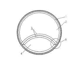
Figs. lA, 1B and 1C show cylindrical
surrounding wall 1 of the hot blast stove, within which
there is a partition wall 3 separating the checkerwork
shaft 2 from the burner shaft 4. The partition wall 3
is joined at each end of the surrounding wall at a wall
joint. Known details of the hot blast stove,W of
affected by the present invention, need not be
discussed here. As the detail views of Figs. lA', 1B'
and 1C' show, the walls 1,3 have layers of pre-pressed
and baked bricks 5,6,7,8,9,10. At the lower region
shown in Figs. 1C and lC', the burner shaft 4 is
provided with additional wall layers of pre-pressed and
baked bricks 8,9,10. An additional intermediate
layer l8 may also be present.
~''~u'' ~% ~.
i
Figs. 1A', 1B' and 1C' show that at the wall
joints, each of the joining bricks, i.e. the bricks
which essentially form parts of both walls, has its own
particular shape determined by its location, so that a
wide variety of joining bricks is required. The
present invention is applicable to such walls or wall
layers mainly or substantially entirely formed of
bricks.
The corresponding views of Figs. 2A, 2A', 2B,
2B' 2G and 2C' of the hot blast stove embodying the
invention show that the pre-pressed and baked joining
bricks are replaced by cast joining elements
11,12,13,14,15,16,17, made of castable refractory
concrete. As shown in the horizontal sections, there
is a cast joining eleiiient corresponding to each pair of
joined layers of bricks. Thus in Fig. 2A', the
walls 1,3 are joined by the cast joining element 11,12
of different shapes: In Fig. 2B', the walls 1,3 are
joined by the cast joining element 13,14. Tn Fig. 2G',
the walls 1,3 are joined by the cast joining elements
15,16,17.
The height of each of the cast joining elements 11-17
may typically be the same as that of one course of the
8
adjoining bricks, or twa courses of the adjoining
bricks. In practice, both have been found suitable.
The illustrated hot blast stove embodying the
invention is otherwise generally the same as that of
Figs, lA, lA' etc.
In one method embodying the invention of
constructing the hot blast stove of Figs. 2A, 2A' etc.,
the cast joining elements were made using separate
casting moulds in the immediate vicinity of the
construction site. In another method of the invention,
the joining elements were cast in situ, as described
below. The choice of method depends on stove
dimensions, local circumstances, accessibility, flow
properties of the castable material etc.
In the method of in situ casting of the cast
joining elements, when one of the courses of the walls
is. being constructed, a spacer material such as felt
for example is placed on the boundaries of the laid
2Q bricks and a shuttering part is placed at the boundary
of the desired joining element which is not bordered by
laid bricks, thus forming a casting mould for the
joining element. Then liquid concrete is poured up to
the desired level.
A joining element of very complicated shape is
thus formed in situ. The joining element may extend in
z~~yl~"~~~r~
9
height over one or more courses of the walls 1 and 3.
The felt forms expansion joints in the structure. In
.. the case of the structure of the hot blast stove in
accordance with the invention it is possible to
concentrate the expansion locations for expansion of
the partition wall 3 at the boundary faces of the
joining elements.
In the invention, there is deviation from the
previous notion that for the joining elements, bricks
have to be used that are preformed, pressed and burned
and subjected to strict requirements, and a new method
is opened up by which construction is considerably
simplified and the costs are reduced as a result.
Suitable castable materials for the cast
joining elements are commercially available low cement
high alumina castables.