Sélection de la langue

Search

Sommaire du brevet 2088748 

Énoncé de désistement de responsabilité concernant l'information provenant de tiers

Une partie des informations de ce site Web a été fournie par des sources externes. Le gouvernement du Canada n'assume aucune responsabilité concernant la précision, l'actualité ou la fiabilité des informations fournies par les sources externes. Les utilisateurs qui désirent employer cette information devraient consulter directement la source des informations. Le contenu fourni par les sources externes n'est pas assujetti aux exigences sur les langues officielles, la protection des renseignements personnels et l'accessibilité.

Disponibilité de l'Abrégé et des Revendications

L'apparition de différences dans le texte et l'image des Revendications et de l'Abrégé dépend du moment auquel le document est publié. Les textes des Revendications et de l'Abrégé sont affichés :

  • lorsque la demande peut être examinée par le public;
  • lorsque le brevet est émis (délivrance).
(12) Brevet: (11) CA 2088748
(54) Titre français: DECONNECTEUR HYDRAULIQUE
(54) Titre anglais: HYDRAULIC DISCONNECTOR
Statut: Réputé périmé
Données bibliographiques
(51) Classification internationale des brevets (CIB):
  • E03C 1/10 (2006.01)
  • F16L 55/07 (2006.01)
(72) Inventeurs :
  • VOLLMER, RUDOLF (Allemagne)
(73) Titulaires :
  • HONEYWELL TECHNOLOGIES SARL (Suisse)
(71) Demandeurs :
(74) Agent: SMART & BIGGAR
(74) Co-agent:
(45) Délivré: 1997-03-18
(22) Date de dépôt: 1993-02-03
(41) Mise à la disponibilité du public: 1993-08-15
Requête d'examen: 1993-06-01
Licence disponible: S.O.
(25) Langue des documents déposés: Anglais

Traité de coopération en matière de brevets (PCT): Non

(30) Données de priorité de la demande:
Numéro de la demande Pays / territoire Date
P 42 04 386.7 Allemagne 1992-02-14

Abrégés

Abrégé anglais


A hydraulic disconnector (10) consists of two backflow
preventers (16, 18) arranged in series in flow direction
of the medium and of an intermediate chamber (20) between
both backflow preventers. The intermediate chamber (20)
is vented to the atmosphere by a venting valve (22). A
differential pressure stabilizer (40) is provided which
controls the differential pressure between the input side
(12) and the intermediate chamber (20) to an approximate
constant value (Fig. 1).

Revendications

Note : Les revendications sont présentées dans la langue officielle dans laquelle elles ont été soumises.


THE EMBODIMENTS OF THE INVENTION IN WHICH AN EXCLUSIVE
PROPERTY OR PRIVILEGE IS CLAIMED ARE DEFINED AS FOLLOWS:


1. In a hydraulic disconnector having an input port and
an output port, and comprising: a first check valve having an
output port and an input port serving as the input port for
the disconnector; a second check valve having an input port
and an output port serving as the output port for the
disconnector; an intermediate chamber connected between the
output port of the first check valve and the input port of the
second check valve; and a venting valve for venting the
intermediate chamber to the atmosphere and controlled by the
pressure differential between the input port of the
disconnector and the intermediate chamber, the improvement
comprising a differential pressure stabilizer connected
between the input port of the disconnector and the
intermediate chamber.


2. The disconnector of claim 1, wherein the
differential pressure stabilizer comprises a housing enclosing
first and second chambers separated by a stabilizer wall
movable in first and second directions to respectively enlarge
and shrink the first chamber and through which the first and
second chambers are in pressure communication, said first and
second chambers respectively in flow communication with the
input port and the intermediate chamber.


3. The disconnector of claim 2, wherein the
differential pressure stabilizer further includes a stabilizer
bias means urging the stabilizer wall in the second direction.


4. The disconnector of claim 3, wherein the stabilizer
bias means comprises a stabilizer spring.


5. The disconnector of claim 4, wherein the venting
valve opens at a predetermined pressure differential between
the input port and the intermediate chamber, and the
stabilizer spring has a preselected spring rate creating a
force on the stabilizer wall equivalent to a pressure
differential greater than the predetermined pressure
differential for the venting valve.


6. The disconnector of claim 5, wherein the first check
valve has a predetermined operating pressure differential, and
wherein the stabilizer spring has a preselected spring rate
creating a force on the stabilizer wall equivalent to a
pressure differential less than the predetermined operating
pressure differential for the first check valve.


7. The disconnector of claim 3, wherein the stabilizer
wall comprises a diaphragm.


8. The disconnector of claim 3, further comprising a
pressure limiter for the intermediate chamber including a


limiter housing including a limiter wall defining a limiter
chamber, said limiter wall movable in first and second
directions to respectively enlarge and shrink the limiter
chamber, said limiter chamber in flow communication with the
intermediate chamber, and limiter bias means operatively
connected with limiter wall, for applying force to the limiter
wall urging the limiter wall in the second direction.


9. The disconnector of claim 8, wherein the limiter
bias means comprises a limiter spring.


10. The disconnector of claim 9, wherein the pressure
limiter's second chamber is vented to atmospheric pressure.


11. The disconnector of claim 1, wherein the venting
valve includes means sensing the pressure differential between
the input port and the intermediate chamber, for venting the
intermediate chamber when said pressure differential falls
below a predetermined pressure differential value, and wherein
the differential pressure stabilizer includes means for
holding the pressure in the intermediate chamber to less than
the difference between the inlet pressure and the
predetermined pressure differential value.


12. The disconnector of claim 11, wherein the
differential pressure stabilizer comprises
i) a housing enclosing first and second chambers


separated by a first stabilizer wall movable in first and
second directions to respectively enlarge and shrink the first
chamber and through which the first and second chambers are in
pressure communication, said first and second chambers
respectively in flow communication with the input port and the
intermediate chamber; and
ii) a bias means in operative connection to the first
stabilizer wall to apply force to the first stabilizer wall
urging the first stabilizer wall in the second direction, said
applied force forming the equivalent of a pressure
differential across the first stabilizer wall greater than the
predetermined pressure differential value.


13. The disconnector of claim 12, wherein the bias means
is a spring.


14. System disconnector comprising two backflow
preventers arranged in a series connection in the flow
direction of a medium and a venting valve venting an
intermediate chamber between both backflow preventers to the
atmosphere which is controlled by the pressure differential
between the input side of the system disconnector and the
intermediate chamber, characterized by the additional
provision of a differential pressure stabilizer between the
input side and the intermediate chamber, wherein the
differential pressure stabilizer consists of a member being
tightly displaceable within a housing and on one hand being


11
biased by means of a spring and the pressure within the
intermediate chamber and on the other hand being admitted by
the pressure of the medium at the input side in order to
change by its displacement the volume of the intermediate
chamber at variations of the pressure at the input side and
therefore to keep the differential pressure
constant.


15. System disconnector according to claim 14,
characterized in that the differential pressure stabilizer is
arranged between two assembling tubes.


16. System disconnector according to claim 14,
characterized in that the differential pressure stabilizer is
an integral portion of the housing of the system disconnector.


17. System disconnector according to one of claims 14,
15 or 16, characterized by the additional provision of a
pressure limiter consisting of a further member being tightly
displaceable within a housing which on one hand is admitted by
the pressure of the medium within the intermediate chamber and
on the other hand is admitted by a spring.


12
18. System disconnector according to claim 16,
characterized by the combination of the differential pressure
stabilizer and the pressure limiter within one housing.

Description

Note : Les descriptions sont présentées dans la langue officielle dans laquelle elles ont été soumises.


20887~8
`_ 1

Hydraulic Disconnector
The present invention relates to such a disconnector
which serves as a safety device and which is inserted in a
drinking water supply pipe to prevent backflow from a non-
drinking water side.
The disconnector consists in known manner of two
backflow preventers in a serles arrangement and a venting
valve controlled by a differential pressure for venting an
intermediate chamber between both backflow preventers. It is
the object of the venting valve to vent the intermediate
chamber when the differential pressure between the input side
and the intermediate chamber falls below a certain value and
to prevent a backflow from the output side to the input side.
Such a known disconnector may be taken from U.S. patent no.
4 478 236.
Those known and altogether approved disconnectors
show a disadvantage in that at a zero flow and with the usual
pressure fluctuations within the supply pipe at the input side
of the disconnector, the differential pressure requested for
safety purposes is shortly falling down, whereupon the venting
valve controlled by the differential pressure responds and
discharges water shortly from the intermediate chamber. This
results on one hand in a non-desired water loss and on the
other hand such a water loss is interpreted by a non-
experienced user as a defective operation of the disconnector.
It is, therefore, the object of the present
invention to further develop the above-mentioned known


~ 69660-21

20887~8


disconnector in such a way that a permanent water loss is
prevented without impairing the safety function of the
disconnector.
In accordance with the present invention, there is
provided in a hydraulic disconnector having an input port and
an output port, and comprising: a first check valve having an
output port and an input port serving as the input port for
the disconnector; a second check valve having an input port
and an output serving as the output port for the disconnector;
an intermediate chamber connected between the output port of
the first check valve and the input port of the second check
valve; and a venting valve for venting the intermediate
chamber to the atmosphere and controlled by the pressure
differential between the input port of the disconnector and
the intermediate chamber, the improvement comprising a
differential pressure stabilizer connected between the input
port of the disconnector and the intermediate chamber.
In accordance with the present invention, there is
further provided system disconnector comprising two backflow
preventers arranged in a series connection in the flow
direction of a medium and a venting valve venting an
intermediate chamber between both backflow preventers to the
atmosphere which is controlled by the pressure differential
between the input side of the system disconnector and the
intermediate chamber, characterized by the additional
provision of a differential pressure stabilizer between the
input side and the intermediate chamber, wherein the


69660-21

2088748
.
2a
differential pressure stabilizer consists of a member being
tightly displaceable within a housing and on one hand being
biased by means of a spring and the pressure within the
intermediate chamber and on the other hand being admitted by
the pressure of the medium at the input side in order to
change by its displacement the volume of the intermediate
chamber at variations of the pressure at the input side and
therefore to keep the differential pressure constant.
With respect to an embodiment shown in the figures
of the attached drawing in the following the design and
operation of the inventive disconnector shall be further
described. It shows:
Fig. 1 a disconnector modified according to the
invention by the insertion of a
differential pressure stabilizer;
Fig. 2 the perfection of a differential pressure
stabilizer;
Fig. 3 a modification of the disconnector
according to the invention; and
Fig. 4 a diagram for explaining the operation of
the disconnector according to the
invention.
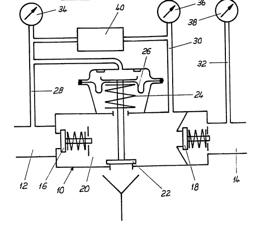
According to figure 1 a disconnector 10 is shown
which comprises in a known manner two backflow preventers 16
and 18 arranged in series between an inlet 12 and an outlet
14. The chamber 20 (intermediate chamber) between both
backflow preventers 16 and 18 is ventable by means of a


69660-21

20887~8

2b
venting valve 22, whereat the venting valve 22 is controlled
by the differential pressure between the inlet 12 and the
intermediate chamber 20 in such a way that a diaphragm 26
biased by a spring 24 compares the pressure at the inlet 12 to
the pressure in the intermediate chamber 20 in order to vent
the intermediate chamber 20 by opening the venting valve 22 in
the event where the differential pressure falls below a
certain value of for instance 0.5 bar.


69660-21

3 2088748

The pressure of the medium which is commonly water at the
inlet 12, in the intermediate chamber 20 and at the
outlet 14 may be connected to pressure gauges 34, 36 and
38 by means of pressure-tapping studs 28, 30 and 32.


According to the present invention a differential
pressure stabilizer 40 is arranged between the pressure-
tapping stud 28, i.e. the inlet 12 and the pressure-
tapping stud 30, i.e. the intermediate chamber 20.
For a man skilled in this art it is obvious that the
differential pressure stabilizer 40 also may be
integrated into the housing of the disconnector 10.

According to Figure 2 the differential pressure
stabilizer 40 consists of a cylindrical housing 42 which
is provided at one side with an inlet 44 and on the other
side with an outlet 46. Between both halves 48, 50 of the
housing 42 a diaphragm 52 is clamped as a displaceable
member biased by a pressure. This pressurized
displaceable member also may be provided by a bellows or
a piston, respectively.

The diaphragm 52 is clamped between two spring plates 54,
and a spring 56 abuts between the spring plate 54 and the
housing 42. On the other side of the spring 56 the spring
plate 54 comprises a circumferential sealing edge 58,
which serves for acting together with an elastical
sealing ring 60 inserted into the housing 42. The inlet
44 of the differential pressure stabilizer 40 is
connectable to the inlet 12 of the disconnector 10, and
the outlet 46 of the differential pressure stabilizer 40
is connected to the intermediate chamber 20 of the
disconnector 10.
From this design the following function results:

4 2088748

The biased spring 56 determines the amount of the
differential pressure at which the diaphragm 52 is
displaced. The biasing of the spring 56 is to be chosen
in such a way that this differential pressure is above
the requested response pressure of the venting valve 22
and is below the pressure at which the first backflow -
preventer 16 is opening. Under those critical operational
conditions, i.e. the disconnector 10 is below the
operation pressure, but having a zero flow the venting
valve 22 remains closed as long as the pressure
difference between the inlet 12 and the intermediate
chamber 20 is smaller than the response pressure of the
venting valve 22. Such a case always occurs when pressure
variations within the supply line result in pressure
drops on the input side 12 of the disconnector 10. Since
the intermediate chamber 20 is limited by two tightly
closing backflow preventers 16, 18, the pressure within
the intermediate chamber 20 is not influenced by pressure
variations on the input side 12 until a predetermined
limit value of e.g. 0,5 bar is attained and the venting
valve 22 is opened in order to achieve a differential
pressure which lies above the predetermined limit value.

By means of the insertion of the differential pressure
stabilizer 40 between the pressure-tapping studs 28 and
30 at a drop of the pressure on the input side a
displacement of the diaphragm 52 under influence of the
biasing spring 56 follows. Since the intermediate chamber
20 is closed by the two backflow preventers 16 and 18, a
pressure drop on the input side and the resulting
displacement of the diaphragm 52 results also in a
pressure drop in the intermediate chamber 20 and,
therefore, it is prevented that the differential pressure
between the input side 12 and intermediate chamber 20 is
influenced by pressure variations on the input side.

~ 5 2~8874~

In other words the pressure within the intermediate
chamber 20 of the disconnector 10 follows the pressure
variations on the input side 12. Therefore, the
differential pressure remains essentially constant. The
input pressure by means of the insertion of the
differential pressure stabilizer 40 becomes the command
variable for the pressure within the intermediate
chamber.

As long as the backflow preventers operate appropriately,
no disturbances occur due to pressure variations at the
input side which would result in an undesired opening of
the venting valve. The function of the differential
pressure stabilizer 40 at an according dimensioning of
the diaphragm is operative up to the underpressure range
on the input side.

Figure 3 shows schematically a modified embodiment of the
disconnector 10 according to the invention, at which
additionally to the differential pressure stabilizer 40 a
pressure limiter 62 is still provided. This pressure
limiter consists of a diaphragm 64 which is biased on one
side by the static pressure within the intermediate
chamber 20 and which is displaced into an end position
against a biasing spring 66 when the static pressure
within the intermediate chamber 20 exceeds a
predetermined value. In lowering under the predetermined
static pressure within the intermediate chamber 20 the
diaphragm 64 is moved by the biasing spring 66, and the
pressure within the intermediate chamber rises which
results in venting of the intermediate chamber. Hereby
the response range can be limited to a minimum pressure
on the input side, which range lies in the overpressure
range.
Figure 4 shows a diagram which illustrates the pressure
behavior with respect to time. The pressure at the input

~ - 6 208~7~8


side 12 is referenced Pl~ and the pressure within the
intermediate chamber 20 is referenced P2. One recognizes
that by the provision of the differential pressure
stabilizer 40 a constant differential pressure ~ p is
provided between the input side 12 and the intermediate
chamber 20. In the event where the static pressure within
the intermediate chamber 20 falls below a predetermined
minimum pressure Pmin, the pressure limiter 62 becomes
operative and maintains this minimum pressure.

Dessin représentatif
Une figure unique qui représente un dessin illustrant l'invention.
États administratifs

Pour une meilleure compréhension de l'état de la demande ou brevet qui figure sur cette page, la rubrique Mise en garde , et les descriptions de Brevet , États administratifs , Taxes périodiques et Historique des paiements devraient être consultées.

États administratifs

Titre Date
Date de délivrance prévu 1997-03-18
(22) Dépôt 1993-02-03
Requête d'examen 1993-06-01
(41) Mise à la disponibilité du public 1993-08-15
(45) Délivré 1997-03-18
Réputé périmé 2008-02-04

Historique d'abandonnement

Il n'y a pas d'historique d'abandonnement

Historique des paiements

Type de taxes Anniversaire Échéance Montant payé Date payée
Le dépôt d'une demande de brevet 0,00 $ 1993-02-03
Enregistrement de documents 0,00 $ 1993-08-06
Taxe de maintien en état - Demande - nouvelle loi 2 1995-02-03 100,00 $ 1995-01-20
Taxe de maintien en état - Demande - nouvelle loi 3 1996-02-05 100,00 $ 1996-01-30
Taxe de maintien en état - Demande - nouvelle loi 4 1997-02-03 100,00 $ 1997-01-30
Taxe de maintien en état - brevet - nouvelle loi 5 1998-02-03 150,00 $ 1997-12-23
Taxe de maintien en état - brevet - nouvelle loi 6 1999-02-03 150,00 $ 1999-01-21
Taxe de maintien en état - brevet - nouvelle loi 7 2000-02-03 150,00 $ 2000-01-20
Taxe de maintien en état - brevet - nouvelle loi 8 2001-02-05 150,00 $ 2001-01-18
Taxe de maintien en état - brevet - nouvelle loi 9 2002-02-04 150,00 $ 2002-01-07
Taxe de maintien en état - brevet - nouvelle loi 10 2003-02-03 200,00 $ 2003-01-06
Taxe de maintien en état - brevet - nouvelle loi 11 2004-02-03 200,00 $ 2003-12-16
Taxe de maintien en état - brevet - nouvelle loi 12 2005-02-03 250,00 $ 2005-01-10
Enregistrement de documents 100,00 $ 2005-07-26
Taxe de maintien en état - brevet - nouvelle loi 13 2006-02-03 250,00 $ 2006-01-09
Titulaires au dossier

Les titulaires actuels et antérieures au dossier sont affichés en ordre alphabétique.

Titulaires actuels au dossier
HONEYWELL TECHNOLOGIES SARL
Titulaires antérieures au dossier
HONEYWELL AG
HONEYWELL GMBH
VOLLMER, RUDOLF
Les propriétaires antérieurs qui ne figurent pas dans la liste des « Propriétaires au dossier » apparaîtront dans d'autres documents au dossier.
Documents

Pour visionner les fichiers sélectionnés, entrer le code reCAPTCHA :


Pour visualiser une image, cliquer sur un lien dans la colonne description du document. Pour télécharger l'image (les images), cliquer l'une ou plusieurs cases à cocher dans la première colonne et ensuite cliquer sur le bouton "Télécharger sélection en format PDF (archive Zip)" ou le bouton "Télécharger sélection (en un fichier PDF fusionné)".

Liste des documents de brevet publiés et non publiés sur la BDBC .

Si vous avez des difficultés à accéder au contenu, veuillez communiquer avec le Centre de services à la clientèle au 1-866-997-1936, ou envoyer un courriel au Centre de service à la clientèle de l'OPIC.


Description du
Document 
Date
(yyyy-mm-dd) 
Nombre de pages   Taille de l'image (Ko) 
Page couverture 1997-02-26 1 16
Abrégé 1997-02-26 1 15
Description 1997-02-26 8 273
Revendications 1997-02-26 6 161
Dessins 1997-02-26 2 41
Page couverture 1993-12-04 1 15
Abrégé 1993-12-04 1 14
Revendications 1993-12-04 2 47
Dessins 1993-12-04 2 44
Description 1993-12-04 6 241
Dessins représentatifs 1999-02-15 1 12
Correspondance 1998-06-30 1 12
Correspondance de la poursuite 1993-02-03 7 263
Correspondance de la poursuite 1993-06-01 1 26
Correspondance reliée aux formalités 1997-01-06 1 30
Correspondance de la poursuite 1996-09-23 1 33
Correspondance de la poursuite 1997-09-15 1 29
Lettre du bureau 1993-08-18 1 34
Demande d'examen 1996-06-18 2 59
Cession 2005-07-26 4 155
Taxes 1997-01-30 1 86
Taxes 1996-01-30 1 82
Taxes 1995-01-20 1 80