Note : Les descriptions sont présentées dans la langue officielle dans laquelle elles ont été soumises.
WO 92/10229 2 0 9 1 ~ fi ~ - PCI /GB91/02117
Powdered medlcament dlspenslng deY~ce.
This invention relates to a dispensing device which
is suitable for the dispensing and administration of a
metered amount of powder. Such a device would be suitable
for the dispensing and administration of pure powder form
drugs or drugs mixed with a suitable carrier agent e. g.
lactose .
Metered dose inhalers are well known and often
comprise a pressurised aerosol dispensing container, The
lo aerosols contain gas propellants in which the powdered
medicament is ~ cpF~n~pd~ on actuation, the aerosol
contents are expelled, through a metering valve, and a
metered dose is propelled into the lungs of the patient.
Research has indicated that some aerosol propellants,
;nr lU,iin~ those used in metered dose inhalers can cause
depletion of the ozone layer in the ai ,~ e. It has
thus become more i ~.,L that such inhalers can be
substituted with metered dose inhalers which do not have
a damaging effect on the environment. Fur~h~ e, such
2 o aerosol systems are not suitable f or some patients .
Several types of powder inhalers are known. Usually
a metered dose of - -i L is initially contained in a
container. The cnnrainPr is often in the form of a
gelatin capsule . The capsule is f irst opened e. g . by
piercing with a pin, and then its contents are dispersed
and expelled by ensuring that airflow, due to the
inhalation of the patient, causes the capsule to rotate.
These powder dispensers have several disadvantages.
It is necessary for the patient to reload the dispenser
WO 92/10229 2 ~ 9 1 ~ 1~ 6 PCI/GWI/0211~
after each dose release, and in some devices the capsules
must be pierced before loading. Complicated r-~-hAnislnc;
are employed to ensure compiete expulsion of powder in
order to provide the correct dose to the patient. This
can make the devices d'ifficult to operate and expensive to
manuf acture .
GB 2102295 and GB 2144997 disclose a complicated
inhaler in which a metered dose of medicament is dispensed
from a storage chamber containing powdered - ~;rAr-nt in
a pelletised micronised form. The inhaler includes a
dosing unit which is connected to a storage chamber f or
the medicament. The dosing unit comprises a perforated
rotating membrane, and spring loaded scrapers to fill the
rotating perforations with medicament. The filled
perforations are introduced to a passage which connects a
propellant container to a nozzle. An amount of propellant
i5 released when the patient depresses two triggers in
succession. The propellant expels the contents of the
exposed perforations towards the nozzle to be inhaled by
the patient. The size of the metered dose is det~rm;nP~i
by the size of the perforations and the number of
perforations that are brought into the propellant passage.
Such a device is expensive to manufacture, and the
dosage accuracy relies on the ef f iciency of the scrapers
to fill the perforations. The perforations often need to
be presented several times to the powdered r -1 i CA- L to
ensure complete filling. For optimum effect the device
also reguires the patient to co-ordinate inhalation with
the operation of propellant release . Many patients f ind
~0 this co-ordinatioh difficult to achieve.
WO 92/10229 2 0 9 i ~6~ PCI /GB91/02117
3
EP 0069715 discloses a device which attempts to
overcome some of the aforementioned problems. There is
disclosed a powder inhaler which is actuated by the
airflow generated by the inhalation of the patient. A
breath actuated device eliminates the problem of the co-
ordination of manual actuation and inhalation. A
propellant is no longer necessary to ef f ect actuation .
The device also uses a perf orated membrane and spring
loaded scrapers to provide a metered dose of medicament.
The patient rotates a manoeuvreing unit by a certain
amount. This rotates the perforated membrane with respect
to the scrapers filling the perforations and exposing a
certain number of them to an air passage. The air flow
generated on inhalation passes through the perforations
and the metered dose is inhaled by the patient. A
rotating means is provided to disrupt the airflow so as to
break up any agyLtyate particles which have been formed in
the dosing unit.
This device has the disadvantage that the airflow
2 0 generated on inhalation passes directly through the
perforations which are then ~eLuL..ed to the dry storage
chamber for refilling. Any powder which has become lodged
in the perf orations may become contaminated by the air,
and this is then mixed with the pure dry powder held in
the chamber. If the perforations become partially blocked
then a full dose of medicament will not be inhaled by the
patient .
It is the object of this invention to provide a
metered dose powder inhaler, wherein the powdered
0 medicament is stored in a powder reservoir housed in the
device. It is a further object o~ the invention to
provide such an inhaler which is simple ln design yet
WO 92/lOZ29 2 0 913 6 6 PCI/GB9l/02~
^ the disadvantages experienced with prior art
dispensers .
In one aspect of the invention there is provided a
powder inhalation device comprising a powder reservoir
capable of containing a powdered medicament and a volume
of air, a metering chamber extending from the powder
reservoir to allow removal of the powdered medicament from
the rcservoir in discrete amounts and a means for
compressing the air in the reservoir wherein a passage is
provided to allow air to vent from the powder reservoir,
through the metering chamber and into atmosphere as the
es~uLa of the air in the powder reservoir is increased.
In a preferred arrangement the reservoir may be
housed in a thin walled cylinder-like structure which
interC~nnPct~ with the main body of the device. The
cylindrical reservoir and the main body may interconnect
by way of a bore located in the main body of the device.
It is preferred that the walls of the cylinder are in
close sliding contact with the bore, whilst allowing air
to pass from the reservoir, through the metering chamber
and into the atmosphere.
In a further arrangement the metering chamber may be
housed in the wall of the cylindrical reservoir. The
chamber may comprise a hole in the wall of the powder
reservoir. The hole is of a predetPrmi nPd size to allow
the desired dosage of powder to pass from the reservoir
ready to be delivered to the main air conduit which
enables the powdered medicament to be inhaled by a
patient. The chamber may be sealed with a fine filter, or
may be a depression in the wall with appropriate venting
or leakage path provided. Certain hole shapes seem to
WO 92/10229 2 0 9 1 3 6 6 PCI /GB91/02117
give better metering repeatability as do different
patterns of air leakage paths. Cylindrical chambers with
their depth equal to the cylinder diameter are preferred.
It is preferred that the metering chamber is f illed
from the reservoir by the instigation of relative motion
between the metering chamber and the powder bulk so that
the air p~e~_ur~: on the powder bulk is increased, forcing
the powder into the metering chamber whilst allowing air
to pass in a small amount through the metering chamber and
vent to ai h-re. Whilst in the device according to the
present invention it is preferred that the powder front
should pass across the entrance to the metering chamber by
relative motion of the powder and the metering chamber, it
has been found that the metering chamber will be filled
- even if the powder ~ulk i5 in contact with the entrance to
the chamber and the air ~s~u~c: above the powder bulk
increased .
The relative motion may be provided by depression of
the cylinder into a bore in the main body of the device,
whilst the bulk of the powder is kept stationary by a
protrusion positioned inside the bore. The cylinder may
be depressed by the patient manually. Alternatively it
may be depressed by the operation of a lever capable of
acting on the cylinder to keep it depressed. It is
preferred that the protrusion is provided with a seal,
such that the inner bore of the cylinder and the
protrusion seal are in sliding air tight contact.
The pressure entered on the powder bulk may be
increased by compressing a volume of air contained above
the powder. It will be realised that although reference
herein has been made to air, any gas may be included
Wo 92/lo229 2 0 91~ 6 ~ PCI/GB91/021Ij~
within the reservoir which does not react with the powder,
e. g. nitrogen.
Although not;`wishing to be bound by theory, t is
likely that a local ~luidising effect of the powder bulk
may take place which aids metering, with the air flow
through the chamber carrying powder into the chamber.
It will also be realised that since the metering
effect seems to be caused primarily by air flDw from the
high pressure region within the air reservoir (and
possibly powder5 to a lower pressure region beyond the
metering chamber, a similar effect could be created by
producing a low ~LeS::-ULe~ region outside the reservoir and
metering chamber, and providing a p~s-uLe differential
between the reservoir and this low ~ =S~UL ~ region to
allow air f low . This is to be understood and included
within the invention as claimed.
In a preferred arr~~, t_, the metering chamber,
once filled, is closed to separate the metered dose from
the reservoir by causing the chamber to move past the
protrusion located in the bore. The metered dose may be
prevented from leaking into the bore in the main body by
ensuring the cylinder walls and said bore are in close
sliding contact, but spaced sufficiently to allow an air
passage. The size of the air pas6age is linked to the
powder particle size and should be sufficiently narrow
that powder within the metering chamber will not escape.
any powdered drugs borne on carriers have an average
particle diameter size of between 20 and 50 (Lm.
Accordingly, the width of the air passageway is preferably
from 10 to 100 Lm, preferably 10 to 50 ~m. The passageway
can be achieved by utilising surface imperfections.
WO 92/10229 ~ PCI/GB91/02117
An exit port may be provided in the bore which, when
aliyned with the metering chamber, allows the chamber to
be emptied. once the powder has been metered it must then
be ejected from the metering chamber. Clearly while more
accurate volumetric metering is achieved with a higher
packing density in the metering chamber, ejection of a
more tightly packed powder is more dif f icult . The f irst
part of this process requires isolation of the metering
chamber from the bulk powder reservoir. This may be
iO achieved by causing the reservoir volume to be moved away
from the metering chamber until a sliding seal moves over
(or over and past) the inner face of the metering chamber.
In this o-~o~ t the seal should be wide enough to
prevent a leakage path occuring f rom the higher pressure
reservoir via the metering chamber to a lower pressure
area behind the sliding seal.
Ejection may take the form of increased air flow
through the metering chamber carrying out the metered
powder, air flow past the chamber, e.g. by a venturi-like
2 0 restriction, creating a negative pressure to suck out the
powder, or by mechanical ejection. Any air ~low
techniques could use the patient inspired air, but it is
likely that dense packing and small metering chamber sizes
may make this difficult particularly in terms of
2~ resistance to air flow. However, there is good potential
during actuation in the specifically described form of the
device to produce a small volume of air, at a ~rcs.~
considerably greater or lower than atmospheric, ( 'high
energy air' ) which can be utilised for dose ejection, and
3 o possibly dispersion .
A further advantage of this technique is that
inspired air does not come into direct contact with the
WO92/10229 ~ 36:~ PCr/GB91/02117~
~ 8
metering chamber and surrounding walls. This could help
prevent any risk of moisture contamination to the bulk
powder from the inspired a~r contaminating the metering
chamber and could be~,a~ anged to help avoid any such
contamination risks s~dùid the patient breath out through
the device.
Mechanical ejection techniques may preferably be
combined with air f low techniques in order to remove
powder which remains attached to the end of the ejector.
The metering chamber may also be in the form of a cup
on a rotable axis. Such a system is described in, for
example, GB 2165159.
It is favoured that the air conduit allows air to
enter an air inlet in the main body and f low to a
raouthpiece, the air flow being caused by the inhalation of
the patient. A venturi-type restriction and a sec~n~iAry
p~':6~ y may be included in the air conduit. The
se~nA~ry p~sAqPway may connect the exit port to the
restriction and further connect a sPc~ ry air inlet to
the restriction. The air flow through the main inlet and
secnn~ry inlet transfers the metered dose to the patient
for inhalation. Alternatively the air flow may be
arranged to f low through the metering chamber .
The even distribution of the powder in the air f low
before it is inhaled is preferably achieved by producing
a turbulent air stream. This may be produced by including
a swirl chamber in the air conduit.
It has been found that the most beneficial effect for
patients is obtained when inspiration is carried out at at
WO 92/10229 ~9 ~ 3 6 B pcr/GB9l/o2ll7
9
least lO litres per minute, preferably at least 15 litres
per minute. This may be achieved by incorporating a
regulator within the inhalator to permit it to work only
at a minimal air flow of, e,g. 10 litres per minute.
i The present invention will be further described by
way of example only, with reference to and illustrated in
the ~ nying drawings in which:-
Figure l is a section view according to an embodiment
of the invention, in the rest position;
l O Figure 2 is a section view according to an Pmhori i r-~t
of the invention in the actuated position.
Figure 3 is a section view of a further Pmho~iir-nt of
, the invention.
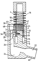
As seen in Figures 1 and 2 an inhalation device
consists of a main body 2 and thin-walled cylinder-like
chamber 4.
The main body 2 includes a bore 6 coaxial with the
cylinder 4 and a protrusion which forms a piston structure
8 inside the bore 6. ~he piston 8 is also coaxial with
2 0 the cylinder 4 .
The piston head 10 is provided with a circumferential
seal 12. The seal 12 ensures that the piston 8 is in
slidable airtight contact with the inner bore 14 of the
cylinder 4.
A passageway 3 is provided by a selection of surface
f inish to allow controlled venting to the atmosphere .
WO 92/10229 2~ g ~ 3 6~6 PCI'/GB91/0211~
1 0
The cylinder 4 is free to move longir~ nAl ly in the
bore 6 but is prevented from rotational movemen~ [ no~
shown]. A spring 16 is coiled coaxially around ~he
cylinder 4. The cylinder walls 18 are in close slidiny
contact with the bore 6 separated by the air passageway 3.
The spring 16 provides a means to~bias the cylinder 4 in
its rest position [ shown in Figure 1 ] .
The main body 2 has a ~oùthpiece 20 connected by a
passageway 22 to a swirl chamber 24. The swirl chamber 24
io is in turn connected to a passage 26 which includes a
venturi-type restriction 28 leading to an air inlet 30.
A side eDtry 32 in the narrow section of the
restriction 28 leads to a secon~lAry passage 34. The
sec~ nrl~ry passage 34 is connected to the main bore 6 by an
exit port 3 6 .
The main body 2 further iDcludes a small bore 38.
The small bore crlnnpctc with the s~con~lAry passage 34 and
is vented at a secondary air inlet 40 close to the air
inlet 3 0 .
0 The inner bore 14 of the cylinder 4, the piston head
10 and the piston seal 12 co-operate together to form a
dry reservoir 42. The reservoir 42 contains a bulk of
finely powdered medicament 44. A volume of air 46 is
trapped above the medicament 44.
The cylinder wall i8 is provided with a metering
chamber 48 comprising a hole in the cylinder wall 18. The
volume of the metering chamber 48 is such that the amount
of medicament which can be contained in that volume is
equivalent to one dose.
WO92/10229 1 1 æo~l3s'6 PCI/GB91/02117
~.
The metering chamber 48 is so positioned in ~he
cylinder wall 18 that when the cylinder 4 is in its
actuated position [ shown in Fiqure 2 ] the meterinq chamber
48 is aliqned with the exit port 36 in the main body ~,
The piston 8 i5 provided with a small sprinq loaded
plunqer 50. The plunger 50 i5 aliqned with the centre
line of the exit port 36. WAen the cylinder 4 is in the
rest position [shown in Fiqure 1] the plunqer i5
restrained from operation by the cylinder wall 18. .
When the cylinder 4 is in the actuated position
~ shown in Figure 2 ] the plunqer is pro j ected into _he
meterinq chamber 48.
The main body 2 of the dispensinq device and the
cylindrical structure 4 are preferably manufactured from
a plastic such 25 polypropylene, acetal or moulded
poly~yrene. They may however be manufactured from metal
or another suitable material.
The piston head seal 12 may be a seal of plastic such
as PTFE, synthetic rubber or natural rubber. The seal 12
may be a cup or lip seal extendinq around the piston head
12 .
In use the patient holds the device such that the
cylinder 4 is located u~yel ~ . The patient then shakes
the device, whilst holding it vertically. The shaking
aids the mixing of the powdered medicament and also
ensures that the powder is deposited at the bottom of the
cylinder 4 in contact with the piston head 10.
WO 92/10229 ~ 2 n g~ PCI/GB91/0211~,
1 2
The patient dèpresses the top of the cylinder 4. The
spring 16 become`s compressed and the cylinder 4 moves down
the bore 6 inside the main body 2.
As the cylinder 4 moves down the metering chamber ~8
passes through the bulk of the medicament 44. At the same
time, the air in the space 4 6 is ~ , _ essed the volume
enclosed by the cylinder wal~s 18 the piston head lO and
the piston seal 12 decreases . A small amount of air f lows
through the powder bulk 44, through the metering chamber
48, through the passageway 3 and into the a~r~ h~^re.
The combined action of the movement of the metering
chamber 48 through the bulk medicament 44 the increase in
pressure on the r-~licA~~nt and the air flow results in the
filling of the chamber 48 with a metered dose of
r - ' i CAr--lt .
The width of the p~ccagrl~ay 3 is such that no
medicament leaks out of the chamber 48.
The patient depresses the cylinder 4 until it reaches
the end of its travel. The patient then inhales whilst
0 keeping the cylinder 4 depressed.
In the actuated position [shown in Figure 2] all the
powdered medicament 44 except that in the metering chamber
48 is sealed in the volume defined by the cylinder walls
18, the piston head lO and the piston seal 12.
~5 When the cyiinder 4 is fully depressed the metering
chamber 48 is aligned with the exit port 36 in the main
body 2 and the spring loaded plunger 50.
WO 92/10229
The plunger 50 is no longer restrained by the
cylinder walls 18 and as it springs forward the powder in
the metering chamber 48 is pushed into the passage 34
through the exit port 36. The plunger is restraineà from
- further movement by suitable means (not shown).
The inhalation of the patient causes air to enter
through the inlet 3 0 . The air~ reaches the venturi -type
restriction 28 and the narrowing of the inlet causes the
air velocity to increase. The air pressure in the
restriction 28 decreases as a result of the increase of
velocity. The drop in ~Les~uLe causes a further stream of
air to enter through the small bore 38 which in turn
causes the metered dose of medicament to be dragged into
the main air stream flowing through the restriction 28.
The metered dose of medicament is carried in the air
stream through the passage 26 into the swirl chamber 24.
The ge tLy of the swirl chamber 24 causes the air
and the powder to follow a circular path. The turbulent
air flow in the swirl chamber results in the dispersion of
2 0 the powder in the air f low.
The particles are carried in the air stream through
the passage 22 to the patient via the mouthpiece 20. The
patient thus inhales air containing a metered dose of
medicament .
After use the patient releases the cylinder 4 and it
returns to the rest position under the inf luence of the
spring 68. The cylinder is provided with a limiting end
stop [not shown] to prevent the cylinder and main body
from becomin~ detached. As the cylinder 4 rises the
2~91~6~
WO 92/10229 PCI/GB91/0211~
- - 14 ~
plunger 50 is caused to retract by the movement of .he
cylinder wall 18 and thej specific shape of the plunger 36.
The enclosed space ~46 returns to its original volume and
the trapped air is no longer compressed.
- The device lS ready for further use.
The inhalation device may be manufactured as a sealed
unit, which is discarded when the level of the powdered
medicament 44 falls below the level of the metering
chamber 4 8 .
Alternative~Ly the reservoir may be refilled through
an opening in the top of the cylinder 4 which is normally
sealed by a plug.
In a further ~.mhod;~~~t of the device, as seen in
Figure 3, an inhalation device consists of a chamber 80
lS which will be within the main body of the device [not
shown] . A volume of powder 82 is t nrl~ within the
chamber 80. Above the powder 82 is a space 84 which is
connected to a means 85 of increasing the pressure of the
air within the space 84.
An orifice 83 leads from the chamber 80 into a
metering chamber 86. This metering chamber 86 is formed
in a plate 87 which is moveable relative to the body
enclosing the chamber 80, in particular the orifice 83.
Remote from the nozzle is an air gap go.
~5 As pressure is increased within the space 84, powder
flows through the orifice 83 into the metering chamber 86.
At the same time, air flows from the space 84 through the
powder 82, through the orifice 83 and metering chamber 86
W0 92/102t9 2 0~ 6 6 PCI/GB91/02117
and out through the air gap 90 which is of such a size to
prevent powder leakage. The ~etering chamber 86 is
completely filled with powder.
The plate 87 is then slid sideways and the chamber 80
containing the metered dose of powder presented to the
dispersion system. In order to refill the chamber, an
airtight removeable lid 8 l is provided .
Suitable drugs which may be used include salbutamol,
beclomethasone dipropionate, b~ A~i~p and sodium
l 0 cromoglycate .