Note : Les descriptions sont présentées dans la langue officielle dans laquelle elles ont été soumises.
209" ~~
BACKGROUND OF THE INVENTION
The present invention deals with the display of information
on a display screen. More specifically, the present invention
provides an apparatus for displaying information regarding the
operation and status of a process control system, while also
allowing the display system to operate in a windows environment.
In a process control environment it is necessary for a
process control system to display large amounts of information to
control system operators. Much of the information communicated
to the operators is of a crucial nature and it is very important
that this information be displayed correctly and in a manner
which the system operators will recognize. Typically, most
information is communicated to the operators via a cathode ray
tube (CRT) or display screen of equivalent type.
Much of the information communicated is very critical to the
proper operation of the control system. Additionally,
information is necessary to maintain safe operation of the
control system. A failure of the display system could cause a
malfunction which in turn could be very dangerous to the process
control system. For example, in a oil refinery certain warning
information must be displayed to the operators to avoid explosion
and/or catastrophe. Therefore, it is important that this crucial
information be communicated to the system operator in an accurate
fashion and that the information maintain its integrity.
Docket No. I2000097 2 11 June 1992
CA 02097558 2000-10-13
64159-1375
SUMMARY OF THE INVENTION
The invention provides a process control system
having a plurality of physical modules each physical module
being operatively connected to a local control network (LCN)
bus communication via the LCN bus being in accordance with a
proprietary protocol, each physical module performing a
predetermined function, and each physical module being
equivalent of each of the other physical modules in terms for
right of access to the LCN bus for purposes of transmitting
data to each of the other physical modules, one of said
physical modules being an operator station module for providing
an interface between an operator and the process control
system, the operator station module including a display system
for the process control system, and further wherein the
operator station module provides an interface between the
process control system and a remote computer system thereby
permitting the remote computer system to display information on
the display system of the process control system, the display
system characterised by: (a) a display generator having at
least one first input port, a first output port, a first
communication port connected to a module bus of the operator
station module, the module bus being operatively connected to
the LCN bus of the process control system and a second
communication port; (b) at least one input device, each input
device being connected to a corresponding number of first input
ports of the display generator, for communicating information
from a user to the display generator; (c) a display device
connected to the first output port of the display generator for
displaying information provided by the display generator; (d) a
module central process unit (CPU), connected to the module bus,
for processing control and display data from the process
control system, the module CPU providing a communication link
to the process control system via the proprietary protocol
3
CA 02097558 2000-10-13
64159-1375
thereby maintaining security and integrity of the process
control system; (e) a coprocessor, having graphics server
logic, the coprocessor connected to the module CPU for
receiving control and display data from the process control
system, the coprocessor further having a port adapted to
receive control and display data from the remote computer
system, the coprocessor further connected to the second
communication port of the display generator, the coprocessor
controlling the display of data on the display device, the data
being displayed being from the process control system and the
remote computer system in response to the control data received
by the coprocessor, the data being displayed in a windows
format, wherein the display generator causes the data received
from the LCN bus of the process control system to be displayed
on the display device whenever the graphics server logic fails.
In order to enhance the capabilities of modern day
process control systems, the display of the process control
system has been upgraded to include windowing capabilities.
These windowing capabilities allow numerous windows to be
displayed on the screen simultaneously. Generally, windowing
capabilities can allow certain display screens to be exported
to other computer systems and can further allow certain display
screens to be imported from other computer systems. The
present invention allows many displays to be imported while
also allowing some displays to be exported. This open
communication of displays provides for a much more flexible and
efficient process control system.
In order to maintain the integrity of the process
control system display, the windowing system must also be
capable of displaying crucial systems information without
destroying the integrity of such information. In the present
invention the control system is directly connected to display
generator, in addition to the windowing system being connected
3a
CA 02097558 2000-10-13
64159-1375
to the same display generator. The direct connection between
the control system and the display generator allows the process
control system to display its crucial information to the
operator via a direct connection. Therefore, when crucial
information is communicated to the system display such
information does not have to go through the windowing system.
3b
2~9~~~8
The maintenance of two sources of graphic display creates a
problem when trying to manage the display capabilities of the
process control system. This problem is solved by allowing the
windowing system to manage the display (a cathode ray tube or
CRT) while also allowing the control system to display
information within a portion of the display. In operation the
windowing system allocates "real estate" on the system display
(an LCN window) in which the process control system can display
information related to the operation of the process control
system. (Information to be displayed by the process control
system is transmitted to the display via the Local Control
Network (LCN), thus this information, when displayed on the CRT,
is referred to as the LCN display). The windowing system sets
the size and location of the LCN window and enables its drawing
capabilities. Furthermore, the windowing system allows the
operator to zoom in on the LCN window and to scroll within the
LCN window if so desired.
It is an object of the present invention to provide a
display system with windowing capabilities which also allows a
directly connected network display. The network display and
windowing system both communicate with a display generator which
eventually projects the display onto the screen (a cathode ray
tube or CRT).
Docket No. I2000097 4 11 June 1992
_ 2p9'~55g
BRIEF DESCRIPTION OF THE DRAWINGS
Other objects, features, and advantages of the invention
would be apparent from the following detailed description taken
in conjunction with the accompanying drawings in which:
Figure 1 is a block diagram showing a process control system
having at least one display;
Figure 2 is a block diagram depicting the typical elements
of the many physical modules within a process control system:
Figure 3 is a block diagram showing the different parts of
the universal station including the display system; and
Figure 4 is a functional block diagram illustrating how the
windowing system operates to open, close and maintain windows on
a display.
Docket No. I2000097 5 il June 1992
DETAILED DESCRIPTION OF THE INVENTION
Before describing the present invention, it will be helpful
to understand the system environment in which the invention is
utilized. Referring to Fig. 1, there is shown a block diagram of
a process control system 10 of the preferred embodiment in which
the present invention can be found. Process control system 10
includes a plant control network 11, and connected thereto,is a
data highway 12, which permits a process controller 20' to be
connected thereto. In the present day process control system 10,
additional process controllers 20' can be operatively connected
to the plant control network 11 via a corresponding highway
gateway 601 and a corresponding data highway 12. A process
controller 20, an interface apparatus which includes many new,
additions, improvements, and features over the process
controller 20', is operatively connected to the pant control
network 11 via a universal control network (UCN) 14 to a network
interface module (NIM) 602. In the preferred embodiment of
process control system 10, additional process controllers 20 can
be operatively connected to plant control network 11 via a
corresponding UCN 14 and a corresponding NIM 602. The process
controllers 20, 20' interface the analog input and output
signals, and digital input and output signals (A/I, A/O, D/I, and
D/O respectively) to process control system 10 from the variety
of field devices (not shown) of the process being
controlled which includes valves, pressure switches, pressure
gauges, thermocouples...
Docket No. I2000097 6 11 June 1992
_ 209~~58
Plant control network (or more simply network) 11 provides
the overall supervision of the controlled process, in conjunction
with the plant operator, and obtains all the information needed
to perform the supervisory function, and includes an interface
with the operator. Plant control network 11 includes a plurality
of physical modules, which include a universal operator station
(US) 122, an application module (AM) 124, a history module (HM)
126, a computer module (CM) 128, and duplicates (backup or
secondary) of these modules (and additional types of modules, not
shown) as necessary to perform the required control/supervisory
function of the process being controlled. Each of these physical
modules is operatively connected to a local control network (LCN)
120 which permits each of these modules to communicate with each
other as necessary. The NIM 602 and HG 601 provide an interface
between LCN 120 and UCN 14, and LCN 120 and data highway 12,
respectively.
Physical modules 122, 124, 126, 128,... of network 11 of the
preferred embodiment are of various specialized functional types.
Each physical module is the peer, or equivalent, of the other in
terms of right of access to the network's communication medium,
or LCN 120, for the purpose of transmitting data to other
physical modules of network 11.
Universal operator station module (US) 122 of network 11 is
a work station for one or more plant operators. It includes an
operator console which is the interface between the plant
operator, or operators, and the process or processes of the plant
Docket No. I2000097 7 11 June 1992
_ 209~55g
for which they are responsible. Each universal operator station
module 122, is connected to LCN 120, and all communications
between universal operator station module 122, and any other
physical module of network 11, is via the LCN 120. Universal
operator station module 122 has access to data that is on LCN 120
and the resources and data available through, or from, any of the
other physical modules of network 11. Universal station module
122 includes a cathode ray tube display (CRT) (not shown) which
includes a video display generator, an operator keyboard (KB)
(not shown), a printer (PRT) (not shown), and can also include
(but not shown) a floppy disk data storage device, trend pen
recorders, and status displays, for example.
A history module (HM) 126 provides mass data storage
capability. History module 126 includes at least one
conventional disk mass storage device such as a Winchester disk,
which disk storage device provides a large volume of programs in
higher level program languages. Typically, the data processing
systems of a computer module 128 have the capability of
communicating with other such systems by a communication
processor and communication lines.
Local control network 120 (LCN) is a high-speed, bit serial,
dual redundant communication network that interconnects all the
physical modules of plant control network 11. LCN 120 provides
the only data transfer path between the principal sources of
data, such as highway gateway module 601, application module 124,
and history module 126, and principal users of such data, such as
Docket No. I2000097 8 11 June 1992
N~9~5~5
universal operator station module 122, computer module 128, and
application module 124. LCN 120 also provides the communication
medium over which large blocks of data, such as memory images,
can be moved from one physical module such as history module 126
to universal station module 122. LCN 120 is dual redundant in
that it consists of two coaxial cables that permit the serial
transmission of binary signals over both cables.
Referring to Fig. 2, there is shown a block diagram of the
common elements of each physical module of the network 11 or the
process control system 10. Each of the physical modules includes
a module central processor unit 38 and a module memory 40, a
random-access memory (not shown), and such additional controller
devices, or units (not shown), which are configured to provide
the desired functionality of that type of module, i.e., that of
the operator station 122, for nonvolatile storage capability for
binary data. The types of data stored by such a mass storage
device are typically trend histories, event histories, ...or data
from which such histories can be determined, data that
constitutes or forms CRT type displays, copies of programs for
the physical modules...
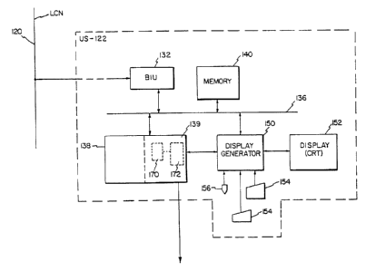
Referring now to Fig. 3, there is shown a block diagram of
the universal station 122. Universal station 122 contains a bus
interface unit 132, a memory unit 140, an internal bus 136, a
CPU 138 which contains a coprocessor 139, a display generator 150
and a display or cathode ray tube (CRT) 152. Local control
network 120 is connected to bus interface unit 132 which is then
Docket No. I2000097 9 11 June 1992
209558
connected to the universal station internal bus 136. Memory 140,
CPU 138 and display generator 150 are also connected to internal
bus 136.
As previously mentioned CPU 138 has an attached coprocessor
139. A direct connection exist between coprocessor 139 and
display generator 150. Coprocessor 139 also has a connection
outside of the universal station which could be attached to other
networks or other computer systems. (e. g., a VAX computer system
manufactured by Digital Electronics Corp., or an IBM computer
system manufactured by International Business Machines, Inc.)
This connection between coprocessor 139 and other computer
systems provides the desired open architecture which shall be
discussed in further detail. Attached to display generator 150
are numerous input devices such as a keyboard 154 and a pointing
device 156. In the preferred embodiment the
pointing device is either a mouse or a touch screen.
Communication between process control system 10 and separate
stand-alone computer systems can provide many benefits and
desired features. One feature is the ability to import different
displays from remote computer systems onto process control system
10. This allows for further processing and communication
capabilities.
Coprocessor 139 provides universal station 122 with the
ability to communicate with remote computer systems. In the
preferred embodiment, coprocessor 139 is a Motorola 68040
microprocessor running the UNIX operating system (UNIX is an
Docket No. I2000097 10 11 June 1992
operating system of the American Telephone and Telegraph Company,
AT&T, and is readily available and well known to those the art).
Coprocessor 139 is sometimes referred to as a UNIX coprocessor.
Coprocessor 139 provides the windowing capabilities for
Universal station 122. Coprocessor 139 runs the X-Windows
windowing system. (X-Windows is a hierarchical windowing system
allowing high speed graphics, which was developed by the
Massachusetts Institute of Technology, Cambridge, Massachusetts
and is well known to those skilled in the art.) Coprocessor 139
and X-Windows further accommodates communication between the
coprocessor 139, and other computer systems. Generally, X-
windows can allow displays to be exported from itself to remote
computer systems. Similarly, displays from remote computer
systems may also be imported to the universal station 122 via a
coprocessor 139.
Display generator 150 is connected to the local control
network 120 via internal bus 136 and bus interface unit 132.
Display generator 150 is also directly connected to coprocessor
139. These two connections to display generator 150 allow for
display 152 to project images from either local control network
120 or coprocessor 139.
Coprocessor 139, running the windows system, controls
display 152 through display generator 150. Windowing commands
are sent to display generator 150 by coprocessor 139 which causes
windows to be generated on display 152. All control of these
windows is done by the windowing system running on coprocessor
Docket No. I2000097 11 11 June 1992
209~~5$
139.
As previously mentioned local control network 120 is also
directly connected to display generator 150. This direct
connection allows local control network 120 to display
information on display 152. (This display of information is
referred to as the LCN display.) However, also as mentioned
coprocessor 139 controls display 152 via display generator 150.
This control of display 152 includes controlling how and when the
LCN display will be shown on display 152.
For the LCN display to be projected onto display 152,
coprocessor 139 must first open a window in which the LCN display
will be projected. Then coprocessor 139 must communicate to
display generator 150 allowing the LCN 120 to overwrite
information in the newly opened window (the LCN window).
Referring now to Figure 4, to open a window coprocessor 139
must first determine the position of the window, the size of the
window and the offset to be used. Within coprocessor is a client
or logic device 180 which calls for the LCN window to be opened.
Client 180 communicates its desire to open an LCN window to a
graphics server 170 (graphics server 170 is a functional block of
the windowing system). Graphics server 170 then communicates the
desire to open an LCN window to an extension or second logic
device 182, which then determines the position, size, and offset
of the LCN window. Second logic device 182 communicates the
position, size, and offset back to graphics server 170. Graphics
server 170 is now ready to transmit the newly obtained
Docket No. 12000097 12 11 June 1992
information to display generator 150.
In the preferred embodiment, display generator 150 and
graphics server 170 are not totally compatible with one another,
therefore special considerations were made to allow for
communication between these two devices. Within graphics server
170 are several layers of operating instructions. Included in
these layers are a device dependent layer 184 and several higher
layers 186. Device dependent layer 184 adjusts communication so
as to allow display generator 150 to understand any communication
sent to it by graphics server 170. An interpreter 172 further
aids the communication between graphics server 170 and display
generator 150.
Graphics server 170, through device dependent layer 184 and
interpreter 172 now communicates the information regarding the
LCN window to display generator 150. This exchange causes the
LCN window to be opened on display 152. Once the LCN window is
open, coprocessor 139 and more specifically, graphics server 170
sends commands to display generator 150 which allows LCN 120 to
overwrite into the newly opened LCN window. The information
overwritten comes entirely from LCN 120 and not coprocessor 139.
Once display of the LCN window has been established,
coprocessor 139, in conjunction with the windowing system,
provides the ability for that window to be moved, to be re-sized
or to be zoomed in upon. However, the contents of the LCN window
are controlled by local control network 120.
Graphics server 170 running within coprocessor 139 also
Docket No. I2000097 13 11 June 1992
2097558
controls the rest of the screen space outside of the LCN window.
Therefore, coprocessor 139 in conjunction with the windowing
system allows other windows to exist simultaneously with the LCN
window. Furthermore, graphics server 170 running within
coprocessor 139 keeps the area around the LCN window clean if
nothing else is displayed there.
The LCN window is used to display crucial operating
information to process control operators. Local control network
120, in conjunction with display generator 150, is capable of
providing an LCN display to display 152 without the assistance of
coprocessor 139. Should coprocessor 139 or the windowing system
fail for any reason, the display generator allows the LCN display
to be projected onto all of the screen space of display 152.
This is a "fall back" mode which ensures the LCN display will not
be lost. Furthermore, when coprocessor 139 opens a window for
the LCN display, the contents of that window are controlled
entirely by local control network 120 and display generator 150.
By allowing local control network 120 to display information on
display 152 when coprocessor 139 should fail insures that crucial
systems information is properly communicated to a display.
Furthermore, should interpreter 172 or any other portion of the
windowing system fail, display generator 150 will also go into
this "fall back" mode, allowing the LCN display to be projected
into all the screen space of display 152.
The present invention has been described in considerable
detail. Those skilled in the art will understand that certain
Docket No. I2000097 14 11 June 1992
modifications and changes can be made to the present invention
without departing from the scope and spirit of the present
invention as claimed in the attached claims.
Docket No. I2000097 15 11 June 1992