Note : Les descriptions sont présentées dans la langue officielle dans laquelle elles ont été soumises.
CA 02099128 2000-04-14
-1-
PULL RING LOCHING MECHANISM
Technical Field
This invention relatfa to locking mechanisms and, more particularly, to
locking mechanisms for pivoting pull rings.
Background of the Invention
It has become common to attach pull rings to small objects to facilitate
manipulating such objects by hand. Typical examples of such objects include
electrical
plugs, hand tools and toys , Such :pull rings are preferably pivotal so as to
pivot from a
storage position in which they are out of the way, to extended operational
position in which
they can be used to manipulate the object. Since such rings must be free to
rotate or pivot
in order to move from the storage position to the operational position, such a
pull ring is
not permanently attached to the object it is intended to accommodate.
As a result ~~f failure to permanently attach a pull ring to the object it is
intended to accommodate, such rings can become detached from the object,
making the
manipulation of the object difficult or even impossible. Moreover, the
dislodgement of
such pull rings from the accommodated object permits the pull ring to be
swallowed by
small children, thus presenting a health hazard. Finally, if the object with
which the pull
ring is used is a flat, very thin electrical plug, the dislodgement of the
ring results in users
attempting to remove the ;plug by inserting fingers under the plug. Such
placement of
fingers, particularly by infants, children and persons without full use of
their hands,
significantly increases the ;hazards ~of electrical shock from the live
electrical pins on the
plug.
Summary of the Invention
The present invention provides an electrical plug comprising a molded plug
body for mounting electrical pins, a removal ring for attachment to said plug
body, said
ring having a retracted position in close contact with said plug body and an
open position
CA 02099128 2000-04-14
- 1(a~ -
disposed away from said plug body to facilitate grasping said ring for removal
of said plug
from a mating socket, a l~xking cavity in said plug body, a rigid locking stub
on said
removal ring for insertion into said locking cavity, and deformable means
completely
closing the entry to said locking cavity for permitting entry of said locking
stub into said
locking cavity by deforming; in response to forces in the direction of said
insertion, and for
preventing exiting of said locking stub from said locking cavity by blocking
deformation of
said deformable means in response to forces in the direction opposite to said
direction of
insertion.
In accordance with an illustrative embodiment of the present invention, a
pivoting pull ring is semi-permanently attached to the object whose
manipulation is to be
facilitated thereby. The attachment is made in such a fashion as to prevent
removal by
normal usage or by significant efforts directed at such removal.
»~, n~ r,-~~~~c n~-ryr,ca~~ inu:,~n
,_. ._.. ._ , ; , ;~
-2-
More particularly, the pivoting pull ring is fashioned with lock
stubs at an angle to the secured end of the pull ring. The object to be
manipulated by the pull ring is fashioned with a lock stub cavity which can be
entered during assembly by the lock stub deforming a lock tab to push the lock
tab out of the way to permit entry of the lock stub into the lock stub cavity.
,
Once the lock stub is in the lock stub cavity, the lock tab returns to its
original
position which locks the lock stub into the lock stub cavity. The lock tab is
fashioned with a gradual ramp on the side away from the lock stub cavity to
facilitate the gradual deformation of the lock tab as the lock stub is forced
over
the lock tab. The side of the lock tab facing the lock stub cavity, however,
is
fashioned with an abrupt vertical face which prevents the lock stub from
deforming the lock tab from the lock stub cavity side, thereby permanently
locking the lock stub into the lock stub cavity.
The present invention will be described in connection with the flat
electrical plug disclosed in applicant's patent 4,927,376, granted May 22,
1990.
It is to be understood, however, that the principles of this invention can be
applied to pull rings for any other objects and, indeed, for fastening two
objects
together with pivotable connection pieces.
It will be noted that, when the present invention is used with a low
profile electrical plug, the pull ring is permanently locked into the plug,
thus
avoiding the possibility of small children swallowing the ring or attempting
to
remove the plug with their fingers, were the pull ring capable of being
separated
from the plug.
One feature of the present invention is the simplicity and low cost
of permanently attaching pull rings to molded objects. The lock stubs on the
pull
ring add very little cost to the pull ring while the lock stub cavity can very
readily
be formed in the object by injection molding 'techniques without significantly
adding to the cost of the molded product.
Brief Description of the Drawings
~ complete understanding of the present invention may be gained .
by considering the following detailed description in conjunction with the
accompanying drawings; in which:
a
,.. ~., ~,,-~.,~ ~ i: :y ,'i .: ~: U nr-,riticoy/n~:~n
77 ~ 7_; i.._
FIG. 1 shows a perspective view of an electrical plug having a pull
ring in accordance with the present invention;
FIG. 2 shows a perspective view of the pull ring of the electrical
plug shown in FIG. 1;
FIG. 3 shows a top perspective view of the electrical plug of
FIG. 1 with the pull ring removed, and showing in dotted .lines the interior
pull
ring cavity for the hooks at the end of the pull ring;
FIG. 4 shows a bottom perspective view of the electrical plug of
FIG. 1 with the pull ring removed, showing the open bottom portion . of the
interior pull ring cavity;
FIG. S shows a partial cross-sectional view of one edge of the
electrical plug of FIG. 1 showing the pull ring about to be inserted into the
pull
ring cavity;
FIG. 6 shows a partial cross-sectional view of the edge of the
electrical plug shown in FIG. 5 showing the pull ring just beginning to engage
the deformable lock tab at the entrance to the lock stub cavity;
FIG. 7 shows a partial cross-sectional view of the edge of the
electrical plug shown in FIG. 5 showing the pull ring fully engaged with the
deformable lock tab at the entrance to the lock stub cavity;
FIG. 8 shows a partial cross-sectional view of the edge of the
electrical plug shown in FIG. 1 showing the pull ring in a retracted position;
FIG. 9 shows a partial cross-sectional view of the edge of the
electrical plug shown in FIG. 8 showing the pull ;ring in a partially open
position;
FIG. 10 is a cut-away edge view of the electrical plug shown in
FIG. 1 showing the pull ring in a retracted position; and
FIG. 11 is a cut-away edge view of the electrical plug shown in
FIG. 10 showing the pull ring in a partially open position.
To facilitate reader understanding, identical reference numerals are
used to designate elements common to the figures.
Retailed Descri~ ion
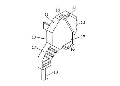
In FIG. 1 there is shown a perspective view of a low profile
electrical pdug 10 having an octagonal body portion 11 and a pull ring 12> The
body portion 11 includes a cutout 13 to facilitate the grasping of ring 12
when
ring 12 is in the retracted position in groove ~4 around half of the upper
edge of
a~,.~ n-~ ~, -,-z~~ ~or-~ria rc9~ in~s~n
., .. " >;
6) aJ ~~- r - G.~ -
body 11. Recesses 15 and 16 provide clearance for rotating ring 12 between the
open position (illustrated in FIG. 1) and the retracted position (lying in
groove 14). A sleeve 17 guides a line cord 18 from the interior of body 11 to
the ,
appliance (not illustrated in FIG. 1). On the obverse side of plug body 11
(not
visible in FIG. 1) are the electrical pins which allow plug 10 to be inserted
into a ,
standard electrical wall socket in order to deliver electrical energy to the
aforesaid appliance. The plug 10 is claimed and disclosed in greater detail in
applicant's patent 4,927,376, granted May 22, 1990.
In FIG. 2 there is shown a perspective view of the ring 12
detached from the plug body 11. As can be seen in FIG. 2, the ring 12 is a
semi-octagonal shape to match the peripheral contour of plug body 11 and
comprises a vertical portion 20, iwo angular portions 21 and 22 and two
horizontal portions 23 and 24. At the ends of horizontal portions 23 and 24
are
seating portions 25 and 26, respectively, which seat in the bottoms of
recesses 15
and 16 (FIG. 1) 'when ring 12 is in the open position. At the ends of seating
portions 25 and 26 are pivot bars 27 and 28, respectively, which act as pivots
for
ring 12 when ring 12 is moved from its closed position to its open position.
In accordance with the illustrative embodiment of the present
invention, at the ends of pivot bars 27 and 28 are lock stubs or hooks 29 and
30,
respectively. As will be described hexeinafter, lock stubs 29 and 30 lock into
lock stub cavities in the interior of plug body 11 in such a manner as to
render
the removal of ring 12 from body 11 virtually impossible. Since it is
necessary
that ring 12 always be available to remove plug 10 from a mating electrical
socket, it is necessary to capture ring 12 in body 11 in such a fashion that
ring 12
cannot be removed from body 11, even with the exertion of considerable effort
such as might be exerted if the ring 12 is inadvertently snagged in moving
furniture. As will be described in detail hereinafter, the lock stubs 29 and
30 are
locked into lock stub cavities by means of deformable entrance tabs which
readily
deform to permit entrance of lock stubs 29 and 30, but which cannot be
deformed to permit removal of lock stubs 29 and 30.
In FIG. 3 there is Shawn a perspective view of the upper surface of
plug body 11 showing the details of the recess 15 in which the ring 12 is
seated.
Recess 15 comprises a shoulder 31 which limits the pivotal movement of ring 12
,
by engaging ring portion 2~ to hold ring 12 in a position perpendicular to the
wn o9it~za~c 'i ~ n n . ,. Pf'T/11~,9t/065fiR
.. ._.._. . ..,~;; :~ ~ :- :i
:_ _ s. ,., f ,
plane of plug body 11. At the same time, the ring portion 25 engages seat
portion 32 of recess 15, also limiting the pivotal movement of ring 12. The
lock
stub 29 fits into a quarter-circular lock stub cavity 33 shown in dashed lines
in
FIG. 3. Also shown in dashed lines in FIG. 3 is a ramp-shaped lock tab 34 at
the entrance to lock stub cavity 34. As can be seen in FIG. 3, lock tab 34 has
a
gentle ramp 35 on the outwardly facing side of tab 34 which facilitates the
insertion of lock stub 29 into lock stub cavity 33. Tab 34 is connected to
plug
body 11 in a cantilever fashion such that tab 34 can be deformed by the
insertion
of lock stub 29 into the entrance into lock stub cavity 33. The deformation of
tab 34 opens the entrance to cavity 33 and allows lock stub 29 to enter cavity
33.
On the inwardly facing side of tab 34, on the other hand, lock tab 34 has an
abrupt vertical face 36 which prevents the deformation of lock tab 34 and
therefore prevents the removal of lock stub 29 from the lock stub cavity 33.
Recess 16, of course, also includes a complementary shoulder portion, a
complementary seating portion, a complementary lock stub cavity guarded by a
complementary lock tab for locking the lock stub 30 in the lock stub cavity.
In FIG. 4 there is shown a perspective view of the bottom of plug
body 11 showing the , recess 15. As can be seen in FIG. 4, the lock stub
cavity 33 communicates with the bottom surface of plug body 11, as does the
complementary lock stub cavity 40 at the other side of plug body 11. While
such
communication with the bottom surface of plug body 11 is not essential to the
operation of the locking mechanism, such communication does facilitate the
formation of cavities 33 and 40 by injection molding techniques in that such
cavities can be formed by protrusions located on the core of the mold. ,
In FIGS. 5 through 7 there are shown partial sectional views of
one edge of plug body 11 showing the insertion of the lock stub 29 into lock
stub
cavity 33. In FIG. 5, the ring 12 is poised outside of plug body 11 in
preparation for insertion. In FIG. 6, the ring 12 is partially inserted into
the
plug body 11 so that the lock stub 29 is just beginning to engage the ramp-
shaped
portion 3S of lock tab 34. In FIG. 7, the lock stub 29 has fully engaged lock
tab 34 and lock tab 34 has been deformed to give lock tab 34 entry into lock
tab
cavity 33: As is evident from FIG. 7, once lock stub 29 clears the edge of
lock
stub cavity 33, lock tab 34 is, free 2o return to ifs undeformed shape and
position,
thereby permanently locking lock.stub 29 into lock stub cavity 33. The only
way
aam .n~ i v zwx .~. ~ Pf'T/i iC01 /(l~~~f)
_. ~,
~. j w _ . -
that lock stub 29 can thereafter be removed from cavity 33 is by destroying or
removing lock tab 34.
In FIG. 8 there is shown a partial sectional view of one edge of
plug body 11 showing the lack stub 29 fully inserted into lock stub cavity 33
and
with ring 12 in the fully retracted position. In FIG. 9 there is shown a
partial ,
sectional view of one edge of plug body 11 showing the lock stub 29 fully
inserted into lock stub cavity 33 and with ring 12 in the partially open
position.
It can be seen in FIG. 9 that the lock stub 12 finds, in lock stub cavity 33,
clearance for rotation beriveen the fully closed position to the fully open
position.
In FIG. 10 there is shown a partial edge view of plug body 11
showing the lock stub 29 fully inserted into lock stub cavity 33 and with ring
12
in the fully retracted position. In FIG. 11 there is shown a partial edge view
of
plug body 11 showing the lock stub 29 fully inserted into lock stub cavity 33
and
with ring 12 in the partially open position. FIG. 10 also shows the recess 15
and
the quarter-circular shape of cavity 33 to provide clearance for lock stub 29
for
the entire range of its motion of ring 12 from the fully closed position to
the fully
open position. In FIG. 11 there is shown a partial edge view of plug body Il
showing the lock stub 29 fully inserted into lock stub cavity 33 and with ring
12
in the partially open position. In FIG. 11 it can be seen that lock stub
cavity 33
provides adequate clearance far lock stub 29 to permit ring 12 to be pivoted
from ,
its fully retracted position to its fully open position.
a
It should also be clear to those skilled in the art that further ~'
embodiments of the present invention may be made by those skilled in the art
without departing from the teachings of the present invention.