Note : Les descriptions sont présentées dans la langue officielle dans laquelle elles ont été soumises.
2101q~2
1 RA~ OUND OF THE lNV~NllON
Field of the Invention
The invention relates generally to an apparatus and method
for collecting and mixing two biological/pharmaceutical liquids.
The invention may be used in connection with a method and
apparatus for collecting whole blood from a donor and mixing the
blood with anticoagulant fluids.
Description of the Related Art
During surgical procedures, blood i8 suctioned from surgical
cavities using a suction wand that is connected to a blood
reservoir for collecting the aspirated blood for later return to
the patient. When handling blood in an extracorporeal device,
blood readily tends to clot, making it unacceptable for reinfusion
into a patient. Thus, it is often desirable to add an
anticoagulant to the blood as it is aspirated. Typically,
anticoagulant is added proximate the point of initial collection,
such as through a side port of the suction wand or into a blood
flow passageway adjacent to the suction wand.
In the conventional system, the suction wand is permanently
in fluid communication with the blood reservoir where typically,
in the case of a hard shell reservoir, a partial vacuum is
created. When the suction wand is used, the infusion of
anticoagulant is manually controlled by an operator.
If large influxes of blood are encountered during a
procedure, it is up to the operator to recognize that additional
anticoagulant is needed, and appropriately ad~ust the
anticoagulant flow rate. In general, the operator will try to
. .
~ 210~2
1 maintain a fixed ratio of anticoagulant to blood. The target
ratio is usually predetermined based upon the anticoagulant being
used and any other relevant data (e.g., the type of surgical
procedure).
A drawback of this system is its inaccuracy. Because the
flow rate and volumes of anticoagulant are manually controlled by
the operator using a roller clamp on flexible tubing, the
procedure has a high degree of variability. Not only are the
initial settings inexact, they have a tendency to change with time
caused by changes in the tubing, fluid height changes, and
pressure changes in the system.
Another drawback of the related art system is that it does
not fit the erratic occurrence and variable flow rate of blood
losses, whereas each time the suction valve is used, varying
amounts of anticoagulant axe usually needed. For example, more
anticoagulant is needed as the suction wand draws only blood than
when the wand draws a combination of blood and air. However, with
the conventional system, unless an operator intervenes, the same
amount of anticoagulant is infused into the blood passageway
regardless of the amount of blood beihg suctioned. Even if an
- operator-intervenes, it is difficult to manually achieve a target
ratio. Thus, with the conventional apparatus and method, it is
possible to infuse too much or too little anticoagulant into the
blood, which could lead to dangerous medical conditions.
SUMNARY OF THE lNV~N-llON
An object of the present invention is to precisely control
~~- the infusion of a first liquid into a second liquid.
-- 2 --
21 n ~ ~ 5 2
Another object of the present invention is to provide
a method and apparatus that provide, a preselected amount of
anticoagulant to a blood collection system, the amount of
anticoagulant infused being a function of a volume of blood in
the collection system.
A further object of the present invention is to
prevent an excess amount of anticoagulant from being infused
into a blood collection system.
Additional objects and advantages of the invention
will be set forth in part in the description which follows, and
in part will be obvious from the description, or may be learned
by practice of the invention. The objects and advantages of the
invention will be realized and attained by means of the
elements and combinations particularly pointed out in the
appended claims.
According to the present invention, there is provided
a blood collection apparatus, comprising:
- means for receiving blood from a patient;
- a reservoir for collecting received blood;
- means for transporting received blood from the
receiving means to the reservoir; and
- means for preventing blood coagulation in
reservoir, the preventing means including:
- means for introducing anticoagulant into the
received blood at a predetermined infusion rate before the
blood leaves the reservoir;
- means for sensing liquid volume in the reservoir
and for transmitting a volume signal corresponding thereto; and
- control means for varying the predetermined
infusion rate of the anticoagulant introducing means in
accordance with a predetermined program and as a function of
the volume signal.
According to the present invention there is also
provided a method for collecting blood from a predetermined
source, the method comprising the steps of:
- receiving blood from the predetermined source;
Bi
- transporting the received blood to a reservoir; and
- regulating a mixture ratio of anticoagulant and
blood in the reservoir, the step of regulating including the
substeps of:
- monitoring a fluid volume within the reservoir
using a sensor;
- outputting a volume signal corresponding to the
fluid volume in the reservoir as sensed by the sensor;
- introducing anticoagulant into the received blood;
and
- controlling the introduction of anticoagulant in
accordance with a predetermined program and as a function of
the volume signal.
The predetermined source may be a patient.
According to the present invention, there is also
provided an apparatus for controlling flow of a medical fluid
into flow of a biological fluid, the apparatus comprising:
- a fluid reservoir;
- transporting means for conveying the biological
fluid into the fluid reservoir;
- conduit means flow connected to the transporting
means, for conveying the medical fluid into the transported
biological fluid; and
- means for regulating a mixture ratio of the medical
fluid to the biological fluid in the reservoir, the regulating
means including:
- means for detecting volume in the fluid reservoir
and for transmitting a corresponding volume signal; and
- control means for varying said medical fluid flow
as a function of said volume signal.
According to the present invention, there is also
provided a method for controlling flow of a first fluid into
flow of a second fluid, the method comprising the steps of:
- transporting the second fluid to a reservoir;
- monitoring a fluid volume within the reservoir
using a sensor; and
~, ~
~,~
2 ~
- regulating a mixture ratio of the first fluid to
the second fluid in the reservoir, the step of regulating
including the substeps of:
- outputting a volume signal corresponding to a fluid
volume sensed by the sensor;
- introducing the first fluid into the transported
second fluid; and
- controlling the introduction of the first fluid
into the second fluid as a function of the volume signal.
The first fluid may be a medical fluid and the second
fluid a biological fluid.
It is to be understood that both the foregoing
general description and the following detailed description are
exemplary and explanatory only and are not restrictive of the
invention, as claimed.
The accompanying drawings, which are incorporated in
and constitute a part of this specification, illustrate several
embodiments of the invention, and together with the
description, serve to explain the principles of the invention.
BRI~ D~SCRIPTION OF TH~ DRAWINGS
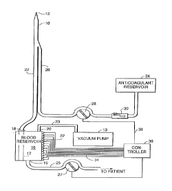
Fig. 1 is a schematic diagram of a blood collection
apparatus in accordance witht the present invention;
Fig. 2 is a perspective view of the blood reservoir
depicted in Fig. 1;
Fig. 3 is a fragmentary sectional view showing a
detail of the blood reservoir depicted in Fig. 2; and
Fig. 4 is a schematic diagram of a second embodiment
of the present invention.
DESCRIPTION OF THE PREFERRED EMBODIMENTS
Reference will now be made in detail to the present
preferred embodiments of the invention, examples of which are
illustrated in the accompanying drawings. Wherever possible,
the same reference
B
~ ~ 2lolqs2
1 numbers will be used throughout the drawings to refer to the same
or like parts.
In accordance with the invention there is provided a blood
collection apparatus including means for receiving blood from a
patient. As embodied herein, and as illustrated in Fig. 1, the
blood receiving means includes suction wand lO such as those
conventionally used to suction blood and other fluids from
surgical cavities. Suction wand 10 includes an opened end 12 for
suctioning blood.
In accordance with the invention there is also provided a
reservoir for collecting received blood, and means for
transporting received blood to the reservoir. As embodied herein,
the transporting means includes tubing segment 22 which connects
blood reservoir 16 with suction wand 10, and pump means such as a
peristaltic pump or a vacuum pump for conveying fluid through
tubing segment 22.
According to a ~irst embodiment of the invention, the pump
means includes vacuum pump 13, and blood reservoir 16 includes a
hard outer shell constructed, for example, of plastic. As
illustrated in Fig. 1, blood reservoir 16 also includes vacuum
port 20, inlet port 18, and outlet port 19. Inlet port 18 is
connected to tubing segment 22, vacuum port 20 is connected to
vacuum pump 13 through tubing segment 23, and outlet port l9 is
connected to tubing segment 25 for returning collected blood to
the patient or conveying it to a blood treatment device. The tip
end 12 of suction wand lO is permanently in fluid communication
with vacuum pump 13, whereby fluid can be suctioned through wand
_ 5 _
~- 2101452
1 10 and tubing segment 22 into blood reservoir 16. Similarly, in
the embodiment of Fig. 3, the pump means includes peristaltic pump
42, directly located in tubing segment 22 for pumping fluid from
suction wand 10 into blood reservoir 16.
Blood reservoir 16 may also include a filter 17 extending
from inlet port 18 along the ~nterior length of the reservoir.
Not only does filter 17 catch any blood clots that may have
formed, but it also dampens fluid flow into the reservoir to
prevent waves and splashes. Preferably a peristaltic pump 27 is
provided in tubing segment 25 for e~ Lying the blood reservoir 16,
and returning the blood directly to the patient, or conveying it
to a device for further processing.
While the preferred embodiments of the present invention are
described in connection with the suctioning of blood from surgical
cavities, the invention has broad medical applications. Even when
used in the medical field, the invention is not limited to a
suctioning apparatus, but may be used in other types of
extracorporeal blood circuits and blood collection devices. For
example, in certain applications, in lieu of the suction wand, the
blood receiving means may include a blood collecting needle for
receiving blood from the arterio-venous system of a patient.
Also in accordance with the invention there is provided means
for introducing anticoagulant into the blood at a predetermined
infusion rate. As embodied herein, the anticoagulant introducing
means includes anticoagulant reservoir 24 connected to suction
wand 10 via tubing segment 26. Anticoagulant reservoir 24 is
typically used for holding a volume of anticoagulant such as
_ 6
2101~52
l heparin or citrate. A pump, such as a varisble speed peristaltic
pump 28, engages tubing segment 26 for pumping anticoagulant
through tubing segment 26 and into tubing segment 22. In
addition, a roller clamp 30 may be provided in tubing segment 26
S to permit manual restriction of anticoagulant flow in the event of
system failure. As is discussed later in greater detail, the
speed of pump 28 is controlled to achieve a predetermined infusi-on
rate for the anticoagulant.
Tubing segments 22 and 26 may be joined in a "Y
configuration adjacent suction wand 10. This structure permits
anticoagulant to be added to the blood immediately as it is
suctioned from a surgical cavity so that coagulation may be
prevented as blood travels through tubing segment 22.
In accordance with the present invention there is also
provided means for sensing li~uid volume in the reservoir and for
transmitting a volume signal corresponding thereto. As embodied
herein, and as best illustrated in Figs. 2 and 3, the sensing
means includes an array of optical detectors 32 extending
vertically along blood reservoir 16. For example, optical
detectors 32 may include a set of thirty-two pairs of light
emitting diodes l9 and phototransistors 21. The detector pairs
are arranged to sense the presence of fluid at their individual
height. According to a prèferred embodiment, the detector pairs
are spaced from each other at lO0 ml intervals. The bottom sensor
is placed at a volume of lO0 ml. Therefore, the volume in the
reservoir can be detected within +/- 50 ml.
- 2101~52
1 Reservoir 16, illustrated in Fig. 2, is substantially
elliptical in cross-section and includes a V-shaped protrusion 17
extending in the vertical direction of the reservoir. Preferably,
the walls of the V-shaped protrusion are oriented at a 90~ angle
to each other. The array of optical detectors 32 are arranged
along V-shaped protrusion 17 so that each of the light emitting
diodes 19 is oriented opposite a corresponding phototransistor 21.
Liquid volume sensed by optical detectors 32 is converted into an
electrical signal which is transmitted through one of signal
lines 34.
In accordance with the invention there is provided co.ntrol
means for regulating the anticoagulant introducing means in
accordance with a predetermined program and as a function of the
volume signal. As embodied herein and as illustrated in Fig. 1,
the control means includes controller 36 electrically connected to
each of the array of optical detectors 32 through signal lines 3~
for receiving the volume signal from the array. Controller 36 is
also connected through signal line 38 to peristaltic pump 28, and
includes a microprocessor that is programmed with an algorithm to
automatically administer anticoagulant by regulating pump 28 in
response to the level detected in blood reservoir 16. Preferably,.
the program of the microprocessor includes an algorithm which
filters out "noise" which may occur when the reservoir is
inadvertently bumped and waves move through the blood supply.
In a preferred embodiment, the blood reservoir has a capacity
of approximately 3.2 liters with detectors spaced along the
vertical direction of the reservoir at 100 ml intervals. The
.
c - 8 -
~101~52
1 average salvage rate may be calculated at each occurrence of
detection by any sensor, as follows:
Qb = ( Vinc + Vpump - Vac~) / Time
where Qb = average rate of blood salvage at the most recent
S sensor change,
Vinc = change in volume in reservoir during sensor change,
acceptable values are +100, -100, or O ml,
Vpump = volume pumped out of reservoir since previous sensor
change,
Vac = volume of anticoagulant pumped into reservoir since
previous sensor change, and
Time = time elapsed from previous sensor change.
As previously indicated, Vinc is a function of the level
detected by the array of sensors 32, and corresponds to the change
in fluid height in the reservoir. Vpump and Vac are calculated as
a function of the number of respective pump revolutions (pumps 27
and 28).
Between sensor changes it is possible to calculate the
maximum (Qb max) and ~ini~um (Qb min) average salvage rates that
could occur. These values are given by:
Qb max = ( V + vpump - vac ) / Time
Qb min = ( V - lOOml + Vpump - Vac ) / Time
where Vpump, Vac, and Time have similar definitions as above
except that they are for the time interval since the most recent
change, and where V = 100 ml if the most recent sensor change
indicated that the reservoir level was increasing, and V = O ml if
the most recent sensor change indicated that the reservoir level
- was decreasing. Between sensor changes the current estimate of Qb
_ g
21014S2
1 is assumed to equal the last calculated value for Qb unless it
exceeds one of the bounds as defined by Qb max or Qb min in which
case Qb is set equal to that bound.
With the above-described system, anticoagulant can be
automatically delivered as a function of either volume of blood
salvaged or the salvage rate. Given that the current desired
practice is to anticoagulate salvaged blood at a specific ratior
one part anticoagulant to R parts of salvaged blood, the pump in a
preferred embodiment may be set to run at Qb dlvided by the ratio
R but not less than a predetermined drip rate. The ratio R is
also selected by the operator and can be changed as desired.
An alternative preferred embodiment, depicted in Fig. 4,
employs a scale 40 in lieu of an array of detectors for detecting
blood volume in reservoir 16. An algorithm can be constructed by
one skilled in the art to calculate the salvage rate and/or volume
in the blood reservoir based upon known weights of anticoagulant
and blood and the known volume of infused anticoagulant. In thè
embodiment of Fig. 4, since an array of detectors is not needed,
blood reservoir 16 may include a conventional flexible plastic
blood bag. If a blood bag is used, a peristaltic pump 42 is
located in tubing segment 22 as illustrated in Fig. 3, as a
substitute for vacuum pump 13 (illustrated in Fig. 1) which would
otherwise collapse a plastic blood bag in absence of an additional
support. Pump 42 could also be used in connection with the
2S embodiment of Fig. 1 in lieu of vacuum pump 13, if desired.
In both the fi-st and second embodiments, the control means
may also include input means, such as a keypad (not shown), for
-- 10 --
21014S2
1 permitting an operator to select various parameters of
anticoagulant infusion. For example, the input means may permit a
user to set minimum pump speéd, a target ratio, or may even permit
manual control by completely overriding the programmed algorithm.
S In another embodiment, (not illustrated) the receiving and
transporting means may be a sponge that is used to absorb blood
from the surgical cavity and is then manually squeezed into a
basin from whence it is transferred into the blood reservoir.
When the sensing means detects the increased volume in the
reservoir, the control means directs an appropriate amount of
anticoagulant directly into the blood reservoir.
Because the above-described embodiments regulate
anticoagulant infusion using detected volume in the blood
reservoir, they can handle any incoming flow rate while still
providing a preselected ratio of anticoagulant to blood. In
addition, since neither the detectors of the first embodiment nor
the scale of the second embodiment detect air suctioned through
suction wand 10, the invention works well regardless of whether
large volumes of air are suctioned along with the blood. Finally,
the invention permits an operator to select target ratios, and
vary those target ratios depending upon the percentage of
anticoagulant desired.
While the invention is described in connection with the
infusion of anticoagulant into blood, the invention is not
intended to be limited to such uses. For example, the invention
has broad applications to other medical systems which will be
apparent to those skilled in the art and which may be constructed
2101~2
without departing from the scope and spirit of the invention.
Additionally, rather than using an array of optical detectors 32
or scale 40 to monitor accumulation of blood and anticoagulant in
reservoir 16, a flow detector may be placed in tubing segment 22
to monitor the rate of flow into the reservoir. The monitored
rate of flow and an appropriate clock for detecting the length of
time the flow rates occur can be used to determine very accurately
the amount of blood being suctioned, and the flow of anticoagulant
can be infused in accordance therewith. Thus, it is intended that
the specification and examples be considered as exemplary only,
with a true scope and spirit of the invention being indicated by
the following claims.