Note : Les descriptions sont présentées dans la langue officielle dans laquelle elles ont été soumises.
210?~7
P-554
A M~HOD FOR NA~ING A ~P~LB~TAL I~P~C~
RE~TR~INT DOOR ~ IN~nM~N~ PAN~ ~Y~M
F~O~ ~IN~ ITARY CO~R
TECXNI~AL FIELD
The invention relates to a method of
making covers for safety air cushion devices, and
more particularly to a method ~or forming a door
and an instrument panel with grain and color
matched cover material thereover, which door is
openable to provide for deployment of an air
cushion from the instrument panel assembly.
15BACK&ROUND OF THE INVENTION
Various methods have been proposed to
form a cover over a deployable air cushion
restraint located within the confines of an
automotive interior part such as an instru~ent
panel. One such method is set forth in U.S. Patent
Number 3,~01,126 and discloses an instrument panel
in which an air cushion device is stored behind a
cover or door which fits within an instrument panel
opening. The instrument panel and t~e cover are
, i, , .. ~ . , - . . ..... . ...................... . . .
",: , - . .. .. .. ..
~- ~.ln,~67
P 554 2
separately fabricated and are assembled following
molding of the component parts of the instrument
panel.
U.S. Patent Number 4,952,351, assigned to
the assignee of the subject invention, discloses a
method form integrally molding a pre-assembled door
within an instrument panel to provide a cover for
a safety air cushion device. The plastic
instrument panel is molded about and over the door
in situ of a mold cavity, and a portion of the
instrument panel is removed which overlies the door
to provide an opening therein to expose the door
for`opening movement with respect to the instrument
panel upon deployment of the air cushion device.
.
However, these methods require the use of ., !''''~
multiple operations to produce the combination of
the instrument panei and the air bag door, and -
20 furthermore it is difficult to match color and ~ ~ -
grain of the cover material.
~ ~'
,
. .
: -"` 2 ~ 7
P-554 3
SIJMM~RY OF THE INVENTION
The invention is a method of molding a
cover material over a preformed door insert and a
plastic panel insert of an interior trim product
for an automobile. The method includ~s the steps
of applying an adhesive over the panel insert and
the door insert, placing the panel insert on a
support, placing the door insert within an opening
of the panel insert on a support tower of the
support, placing a unitary cover material over the
panel insert and the door insert, and forming the
cover material about the door insert and
continuously over the panel insert. The method
also includes cutting the covered door away from
the covered panel insert and removing the~covered
door from the support and thereafter removing the
covered panel insert from the support.
By forming a unitary cover material over
both the door and panel inserts, both grain and
color are consistent in the covering material for
the two inserts. Furthermore, waste of the cover
material ls decreased by forming the cover over the
o 25 panel insert with the door insert located within
~ . i ~.. .. ~ ........ . . . .
~ t. ~67
P-554 4
the door insert opening of the panel insert member.
In prior methods, the outer covering material
covered such door insert opening and constituted
waste material when cut away to form the door
insert opening.
BRIEF DESCRIPTION OF THE DRAWINGS
The advantages of the invention will
become more readily apparent when taken in
conjunction with the accompanying drawings wherein:
Figure 1 is a persp~ctive view of an
instrument panel including the door construction of
: ..
the pre ent in~ention;
Figure 2 is an enlarged perspective view,
partially sectioned showing the instrument panel
and door combination of the present invention along
lines 2-2 of Figure 1 looking in the direction of
the arrows;
Figure 3 is an enlarged perspective view,
partially sectioned showing the instrùment panel
and door combination of the present invention of
Figure 2 in a partially deployed position; and
`
: . ,
'
2ln~
P-554 5
Figures 4a-d are schematic views o~ the
method used to fabricate the constructions shown in
Figures 1-3.
DESCRIPTION OF THE PREFERRED EMBODIMENT
. .
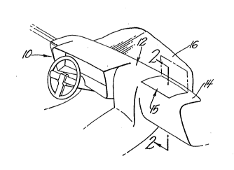
A vehicle compartment 10 is shown having
an interior trim component representatively shown
as an instrument panel 12 in Figures 1 and 2. For
purposes of discussion, the invention will be
incorporated in the illustrated instrument panel 12
-with it being understood that both the method and
product formed by the method of the present
- invention are equally suitable for use with other
vehicle components including door panels, console~
and headliner components.
The instrument panel 12 more particularly
includes an upper surface 14 which is located
forwardly and below the front windshield 16 of the
vehicle. on the passenger side of the upper
surface 14 is a passenger side supplemental impact
restraint (SIR) door 15 which covers and contains
a restraint device or air bag system 17. As
illustrated in Figures 2 and 3, the air bag system
P-554 6 ~i.0~67
17 includes an air bag 19 folded in a compartment
21 behind the door 15. The door 15 is placed
within an opening 23 of the instrument panel 12 and
connected thereto by a hinge or tether 25 which,
upon deployment of the airbag system 17, the door
15 will open from the panel 12 pivoting along the
hinge 25 that restrains movement of the door 15
into the passenger compartment. It is to be
understood that the door 15 can take any shape and
is schematically represented by the following
description.
The upper surface 14 is formed by an
outer cover material or skin layer 18 which in one
: '- ' .::. -
working embodiment is made from a relatively softpolyvinyl chloride resin material (PVC). In the
preferred embodiment, the cover material 18 is an
expanded vinyl material which includes a composite
of at least two layers of material bonded together,
such as a thin vinyl (PVC) outer film layer and an
interior expanded urethane foam layer adhered to
one another at an interface therebetween to form a
resultant laminated material.
'~
P-554 7 ~1 02567
The outer cover material 18 covers and
contains a panel insert member 20 and door insert
member 22. The panel insert member 20 is molded to
the desired configuration in a standard foam
molding operation, as commonly known in the art.
The panel insert member 20 includes a rigid form 26
made of plastic or metal. The panel insert member
20 includes an opening 23 therein for placement of
the SIR door 15. The door insert member 22 is made
of light impact resistant material 28 such as
aluminum or other suitable high strength material.
The resultant product of the instrument
panel 10 includes the layer of skin or cover
material 18 formed over the panel insert member 20
and the door insert member 22. The cover material
18 is adhered to the inserts 20, 22 as commonly
known in the art, such as by a spray adhesive 30.
The method of the subject invention
produces the passenger side visible SIR door 15 and
the full instrument panel 12 in a single cover
forming operation. The method applies a single,
uniform continuous sheet of the cover material 18
to the panel insert member 20 and the door insert
P-554 8 ~.t ~ 5 7
member 22 in a single operation such that the door
15 and instrument panel 12 will be covered by the
same material with similar characteristics, such as
color and grain. Accordingly, the method avoids
possible color shift in methods where the door and
instru~ent panel are covered by an outer material
cut different manufacturing stations.
The cover material 18 is generally a PVC
material which is of a softness and appearance, and
can include a grain therein, i.e. simulated
leather. Therefore, the grain of the cover
material 18 can be perfectly matched, along with
eliminating color shift between the parts as can
occur when different piece~ of skin are utilized.
Lastly, the cover material 18 for the door 15 is
made from a section of material over the panel 12
that otherwise would become scrap and waste in
forminy the opening for tha door in the panel 12.
The insert members 20l 22 are washed and
dried to prepare for the process. As best
illustrated in Figures 4a-4d, the method of making
the trim panel 10 includes Cpraying both the
preformed panel insert member 20 and the preformed
- , . .... , ............ . ..... ., " ,.... ~
.
.
~1~2fi~7
door insert member 22 with an adhesive layer 30 and
is subsequently oven dried. Thereafter, a support
mold or member 32 is provided for supporting the
panel insert member 20 and door insert member 22
-5 during application of the cover material 18. The
support member 32 includes a support surface 34 of
a shape complimenting the shape of the panel insert
member 20, and a support tower 36 extending
vertically from the surface 34 having a support
head 38. The panel insert member 20 is loaded onto
the support surface 34 such that the support tower
36 extends through and above the opening 23.
Thereafter, the door insert member 22 is loaded on
the support head 36 o~ the support tower 38.
Vacuum cups 42 connected to the support member 32
are activated to hold the insert members 20, 22
securely in position (Figure 4a). The support
member 32 then rotates into a preheat oven that
heats the sur~ace of the inserts 20, 22. The
insert members 20, 22 must be brought up to a
temperature where the adhesive meets the expanded
vinyl material. Thereafter, the æupport member 32
is rotated to a forming station.
: . , ,, : ' .
,
,
\
P-s54 1~ 567
' :''
With reference to Figure 4b, the heated
sheet of skin or cover material 18 is placed over
the insert members 20, 22 adjacent the adhesive
layer 30. A vacuum 44 connected to the support
member 32 is activated to cau~e vacuum forming of
the cover material 18 against the inserts 20, 22.
The support member 32 includes a plurality of
aperture.s 46 therein, as commonly known in the art,
to allow the vacuum suction to occur through the
support member 18. Plug assists 48 (Figure 4c) are
utilized to form the skin layer 18 around the door
insert m2mber 20 and the opening 23. The plug
assists 46 push the cover material 18 into deep
draw areas. The mold.ing of a cover ma~erial 18
adjacent a substrate is commonly known and general
vacuum molding principles are applied herein to
perform the similar function. $he support member
32 may rotate to a cooling station.
Thereafter, as illustrated in Figure 4d,
the cover material 18 is trimmed or cut between the
door insert member 20 and the opening 23 to
separate the covered door 15 from the instrument
panel 12. The door 15 is removed from the tower
36, and thereafter the instrument panel 12 is
" ' , ' , .
; . .: ,
~.': ,
21~ 6~
P-554 ~1
removed from the support member 32. The door 15
and panel 12 may thereafter be assembled and placed
in the vehlcle compartment 10 as commonly known in
the art.
The invention has been described in an
illustrative manner, and it is to be understood
that the terminology which has been used is
intended to be in the nature of words of
description rather than of limitation.
Obviously, many modifications and
variations of the present invention are possible in
light of the above teachings. It is, thsrefore, to
be underetood that within the scope of the appended
claims the invention may be practiced otherwise
than as specifically described.
,:
.. ..
.. ,,,,~ , . ... .