Note : Les descriptions sont présentées dans la langue officielle dans laquelle elles ont été soumises.
2 ~ ~ 3 ~ 4 ~ ~
INDICATOR FOR A DEVICE FOR THE INFLATION OF, MORE PARTICU-
LARLY, A CONTAINER OR A FLOATING BODY OF AN ITEM OF LIFE-
SAVING EQUIPMENT.
BACKGR0UND OF THE INVENTION
The present invention reLates to a device for the inflation
of, more particularly, a container or a floating body of an
item of lifesaving equipment with compressed gas from a
diaphragm-seaLed compressed gas container which, within the
region of the container neck, is provided with an external
thread and which, with the container neck, can be screwed
into a receiving aperture in a housing which is provided
with a corresponding internal thread and whose gas content
is released by opening the diaphragm by means of an opening
striker disposed in the housing, which can be moved both by
means of a hand lever and/or by the force of a spring, against
the diaphragm.
An automatic device is already known which is comprised of a
basic body, into which the compressed gas bottle is screwed.
In addition, a second, separate part exists in which a spring
element is disposed which is tensioned by being screwed in or
by being fitted together and which produces the requisite mo-
mentum in order to, in a known manner, by the interposition
of a tablet that dissolves in water, thrust a pointed striker
through the sealing diaphragm for opening the compressed gas
bottle (DE-AS 27 15 132).
In this case the compressed gas bottle has to be screwed in
completely while possessing a certain pretension in order to
make a perfect operation possible. Vibrations or frictional
influences due to external effects or actions must not be
detrimental to the compressed gas bottle in its screwed con-
nection with the equipment body since the possibility of a
~3~41 ~
-
detachment and, with this, an impairment of the reliability could
arlse.
Also in other manually operated and/or automatic
devices the problem exists that a precondition for a faultless
operation ensuring an optimal reliability consists in that the
compressed gas container is screwed in at least up to a planned
point, at which an adequate screwing-in depth and an adequate
pretension is ensured.
Especially in a device of the type mentioned here in
which provision is made for the compressed gas container to
pretension at the same time the spring which moves the opening
striker during the release against the diaphragm when the
container is screwed into the receiving aperture of the housing,
it is of great importance to ensure that the compressed gas
container is screwed sufficiently far into the receiving aperture
so that not only a more secure fit of the compressed gas
container is ensured, but also a sealing of the compressed gas
container and an adequate pretensioning of the main spring is
achieved.
That is why it is the technical problem of the present
invention to develop further a device of the type stated in the
beginning in such a way that an indicating means is provided
which indicates the screwed-in state of the compressed gas
container, i.e., which provides an indication as to whether the
compressed gas container is screwed in far enough into the
receiving aperture so that a reliable operation of the device is
guaranteed.
23589-140
~ -
SUMMARY OF THE INVENTION
According to a broad aspect, the invention provides a
device for the inflation of a container or a floating body of an
item of lifesaving equipment with compressed gas from a
compressed gas container, the device comprising: a housing
including a receiving aperture for receiving a neck of the
compressed gas container; an opening striker disposed in the
housing and movable by means of a hand lever or by the force of a
spring, for opening a diaphragm of the compressed gas container
to release the compressed gas therefrom; means displaceably
guided within the housing, for indicating when the compressed gas
container is screwed into the receiving aperture, the indicating
means being displaced by the compressed gas container from an
initial position; and means for supporting the indicating means,
with the aid of a spring element, against a displacement from the
initial position.
Preferably, the indicating part which is displaced from
an initial position during the screwing in of the compressed gas
container can be utilized in such a way that the same, in an
appropriately far displacement from the initial position, brings
about in any form whatever an indication which shows the operator
that the compressed gas container is screwed in far enough. A
sufficiently far screwing in does in this connection ensure that
the compressed gas container was also screwed in with an adequate
torque since, in an increasing screwing in, the counteracting
23589-140
B
torque rises slowly and, when impinging upon a pertinently
constructed fixed or spring-loaded stop, the torque is increased
correspondingly so that a reliable fit of the compressed gas
container combined with an appropriately far screwing in is
ensured.
Preferably, the indicating part furthermore ensures
that, if the device is conceived in such a way that also the main
spring is pretensioned by the compressed gas container, it is
made certain that an adequate pretension is applied which
guarantees a reliable functioning of the device. It is
immaterial in this case whether, when the container is screwed
in, a compression spring is compressed or a tension spring is
drawn apart. What is essential here is that the screwed-in state
signalled by the indicating part ensures that the pretension in
the main spring suffices.
A further advantage has to be seen in that, preferably
when screwing into the receiving aperture until the indication
takes place by the indicating part, a sufficiently deep screwing
in of the compressed gas container also takes place to the effect
that the diaphragm of the compressed gas container has been
displaced sufficiently close to the spike or the point of the
- 3a -
23589-140
B
4 - ~ ~ ~ 3 ~ 4 ~
opening striker so that the latter, in the event of a manual
release or by a pertinent automatic element, is certain to
reach the diaphragm. In this connection it is provided that
the indicating part, when being displaced from its initial
position into its terminal position, will, in said posi-
tion, at least with a certain section of its external or
casing surface, appear on the housing surface so as to signal
the achieved adequate screwed-in state to the user.
By preference it is provided that, in the housing, a perfora-
tion extending from the housing exterior to the indicating
part is constructed in the form of a viewing window thus
making a view of the external casing surface of the indicating
part possible. It is preferably provided in this case that
the externaL or casing surface of the indicating part pos-
sesses a first subsurface which, in any form whatever, con-
stitutes a marking. A certain contouring of the surface may
be provided in this connection, for instance, a knurling or
a wavy contour. It is advantageous, however, to alternatively
or complementarily hereto apply a coating of paint, e.g. in
the form of a coat of red paint, which signals that the de-
vice is not adequately screwed in as yet. It is furthermore
provided that a second subsurface of the external or casing
surface likewise possesses an appropriate surface configura-
tion in the form of a contouring and/or a coat of paint in
the manner explained in the foregoing, in which case a green
coat of paint may signal that an adequate screwed-in state
exists. Provision is advantageously made in this case for the
first subsurface to be located in the initial position of the
indicating part within the region of the perforation in the
form of a viewing window so that it is signalled to the user
that the compressed gas container is not as yet screwed in
at all or is not yet screwed in to an adequate screwing in
depth. It can also be provided that the subsurface, in this
state, projects from the housing through an appropriate
4 1 ~
-- 5
housing aperture and thus signals a state of danger. On top
of that it is then provided that, when the indicating part
is moved, by the screwing in of the compressed gas container,
into its terminal position or at least into a position that
corresponds to an adequate screwing in depth of the indica-
ting part, the second subsurface is located in front of the
viewing window or in some other way manifests itself to the
outside so as to signal to the user that an adequate or the
desired screwing in depth of the compressed gas container
has now been reached. In this state, when the e.g. green area
signals the adequate screwed-in state through the viewing
window, an adequate screwing in moment has been applied en-
suring a secure mounting of the compressed gas container and,
moreover, an adequate screwing in depth has also been reached.
In an automatic device in which the primary spring is tensio-
ned with the aid of the screwing in operation, an adequate
pretensioning of the primary or working spring has then also
been achieved in this state.
In this case it is advantageously provided for the indicating
part to be supported by a spring element against a displace-
ment from the initial position. On the one hand, this leads
to it being ensured that the screwing in moment is increased
during the screwing in operation. It is also ensured, further-
more, that the indicating part, when the compressed gas con-
tainer is unscrewed once more from the device, again moves
automatically and immediately back into its initial position,
in which it signals the state of danger connected with an in-
adequate screwed-in state. The spring element can in this
case be realized in different ways. The employment of one or
of a plurality of individual springs is just as conceivable
here as is the advantageous conception of the spring element
being a helical spring inserted into an annular groove
constructed concentricaLly relative to the central longitu-
dinal axis or that the spring is a spring ring disposed in
an annular groove construted concentrically relative to the
central longitudinal axis. The spring ring may in this case
be comprised of a deformable plastic or it can be a vulcani-
zed-in, corrugated spring ring or washer. On this occasion
the use of rubber, caoutchouc or suchlike is also possible.
The spring parameter of the spring element which, after all,
is made up of one or several springs or by the spring ring,
will in this case have to be selected in such a way that an
adequate displacement path of the indicating part is ensured.
It is advantageously provided in this case that the perfora-
tion possesses a substantially rectangular configuration and
that the cross-section of the perforation has a height in
the direction of the central longitudinal axis which corres-
ponds to approximately half of the displacement path of the
indicating part from its initial position into its terminal
position. The perforation is here disposed in such a way that
the second subsurface of the external or casing surface of
the indicating part only is displaced entering the viewing
area into the region of the perforation when the indicating
part has already covered at least 50% of its displacement
path, since it is ensured then that the compressed gas con-
tainer is screwed in sufficiently deeply and that an adequate
torque has also been applied since, after all, 50% of the
travel stroke of the spring have already been covered by then.
As soon as the second subsurface, to be designated as indi-
cator strip, then appears in the viewing window, it is ensu-
red that the device is adequately operative.
It can be provided here that, when the compressed gas contai-
ner is screwed in, the indicating part is acted upon on a
-
~ 7 ~ 2~3~4~
front side of the compressed gas container by the front-end
rim of the compressed gas container which surrounds the dia-
phragm and is dispLaceable for at least a part of the scre-
wing in path of the compressed gas container in the screwing
in direction.
If provision is made on the device for the receiving aperture
of the housing to be constructed in a displacement part and
that, during a screwing in and tensioning operation, a hou-
sing surfaces located within the housing aperture can be ac-
ted upon by the compressed gas container by means of the
front-end rim of the compressed gas container surrounding
the diaphragm and the displacement part projects from the
housing by at least a part of the screwing in path of the
compressed gas container contrary to the screwing in direc-
tion, that also in this case, during the screwing in of the
compressed gas container, the indicating part, on its front
side, can be acted upon by the compressed gas container by
means of the front-end rim of the compressed gas container
surrounding the diaphragm and is displaceable by at least a
part of the screwing in path of the compressed gas container
in the screwing in direction, while, in this case, a relati-
vely rigid spring element is then selected and also the di-
mensioning of the spring element and of the viewing window
are selected in such a way that only a small displacement
in the housing has to be provided in order notto unnecessa-
rily extend the entire screwing in path.
It can generally be provided that, during a screwing in ope-
ration and a tensioning operation possibly effected at the
same time, the indicating part is acted upon by a ring, lug,
cam or surface area of the compressed gas container and that
it is displaceable by at least a part of the screwing in
path of the compressed gas container in the screwing in di-
rection. What is essential in this connection is that the
4 ~
-- 8
displacement of the indicating part is brought about direct
or indirect by the compressed gas container so that it is
at aLl times ensured that the compressed gas container is
screwed in sufficiently far.
Advantageous constructions and expedient further developments
of the invention are characterized in the subclaims
BRIEF DESCRIPTION OF THE DRAWINGS
Embodiment examples of the invention are described in greater
detail below with the aid of the drawings. Thus
~ i 9. 1 shows, in a vertical and partially sectioned illus-
tration, an inflation device;
~ i 9. 2 shows, in a - compared with Fig.1 - reduced illus-
tration, the device according to Fig.1 in a non-
sectioned view;
~ i 9. 3 shows a view of the device according to Fig.1 which,
in comparison with Fig.1, is turned through 90~;
~ i 9. 4 shows, in a vertical partially sectioned represen-
tation, a further embodiment of the device;
~ i 9. 5 shows, in a vertical partially sectioned represen-
tation, a further embodiment of the device;
~ i 9. 6 shows, in a view from the top, the device according
to Fig.5;
~ i 9. 7 shows, in a vertical partially sectioned represen-
tation, a further embodiment of the device;
~ i 9. 8 shows, in a vertical partially sectioned represen-
tation, the device according to Fig. 7 in an over-
all view, and
~ i 9. 9 shows, in a non-sectioned representation, the de-
vice according to Fig.8.
- 9 ~ 3 ~ 4 ~
DETAILED DESCRIPTION OF THE PREFERRED EMBODIMENT
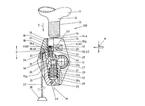
In Fig.1, a device 100 for the inflation of a floating body
not depicted in the drawing of a likewise non-depicted item
of lifesaving equipment with compressed gas is illustrated,
wherein the device is shown in the non-tensioned state with
the compressed gas container 11 being depicted not screwed
into the housing 10. The compressed gas container11, which
is constructed in the form of a merely indicated compressed
gas bottle, is, within the region of the container neck 12,
provided with an external thread 13 and sealed with the aid
of a diaphragm 14.
In a housing bore 15 which, in its upper section, is provided
with an internal thread 16 and which can be caused to commu-
nicate, via a branch duct 17 and an air supply connection
piece indicated at 17a, with an item of lifesaving equipment
to be inflated which is not shown, the indicating part 18 is
disposed, which is constructed in the form of a sleeve and
extends, with one of its front sides, as far as into the
region of the upper section of the housing bore 15 with the
internal thread 16 and which, consequently, when the com-
pressed gas container 11 is screwed in, is acted upon by the
front side 14a of the container neck 12. Within the region
of the front-side 19, an annular groove 20 is constructed
into which a sealing ring 21 is inserted which is acted upon
direct by the front-side 14a of the container neck 15 and,
when the compressed gas container 11 is screwed in, results
in a sealing so that the gas flowing forth from the perfora-
ted diagphragm 14 is able to flow only through the perfora-
tion 22 in the sleeve 18 and is, within the housing bore 15,
conducted to the branch duct 17. At the oppositely located
end 23 of the indicating part 18, the same is supported
with the front face 24 upon a spring element which, in this
- 1 o ~ 4 t
embodiment, is a helical spring 25 which is fitted into an
annular groove 26. In the part located on the right-hand
side of the drawing and not depicted therein of the housing
bore 15, a pertinent retaining means is provided, with the
aid of which the indicating part 18 is undetachably retained
in the housing 10.
In a further section 15a of the housing bore 15, opposite
the indicating part 18, the opening striker 27 is displa-
ceably mounted, which, in its normal position, reaches with
the spike 28 as far as into the region of the front side 19
of the indicating part 18 and which, by means of its actua-
ting end 29, can be inserted through the perforation 22 and,
when the compressed gas container 11 is screwed in, through
the diaphragm 14. At its lower section 29a, the actuating
end 29 possesses a terminal section 30 which, in comparison
with the diameter of the cylindrical actuating arm 29, is
enlarged and which has a hood or cap-shaped configuration and
between the latter and the housing shoulder 31, the return
spring 32 is supportingly disposed at both ends. This return
spring 32, disposed in the enlarged perforation section 15b
of the housing perforation 15, holds back the opening striker
27 so that no unintentional damage to the diaphragm 14 can be
caused. Underneath the terminal section 30, the hand lever 33
is disposed so as to be swivelable about the axis 34 which is
integral with the housing and disposed at a distance from the
central longitudinal axis M, said hand lever being construc-
ted in a two-armed fashion, in which case the one swivel arm
35, when swiveled about the axis of rotation 34, actuates
the terminal section 30 and displaces the same coaxially
to the central longitudinal axis M of the device in the direc-
tion of the compressed gas container so that, by means of
the spike 28, the diaphragm 14 is perforated, for which a
traction strap 37 with a handle 38 is attached to the
4 ~ ~
- 11 -
second swiveling arm 36 of the hand lever 33. Since the arms
35,36 of the hand lever 33 possess a suitable angle relative
to each other and, owing to the great length of the swivel
arm 36 in comparison with the stub arm 35, suitable lever
conditions also exist when the traction strap 37 is actuated,
it is possible for the hand lever 33 to be swiveled without
any substantial expenditure of force anticlockwise about the
axis of rotation 34 so that the diaphragm is perforated and
the compressed gas flows in.
In order to ensure the reliability of this operation, the
following is provided in the device 100 according to the in-
vention.
The indicating part 18, on its external casing surface 18a,
possesses a first annular subsurface 39 which, by way of
example, is provided with a coat of red paint 40 in the form
of a surface coating. This first subsurface 39 is located
within the lower region of the casing surface 18a of the in-
dicating part 18 which faces the end 23 and, above the first
subsurface 39, a second annular subsurface 41 provided with
an e.g. coat of green paint 42 is formed. In addition, in
the housing 10, a perforation 43 is constructed which extends
from the housing exterior 10a up to the indicating part 18
and forms a viewing window 44 which is disposed in such a
way that, through the viewing window 44, the first subsurface
39 can be seen at least in part when the indicating part 18
is in its initial position depicted in the drawing.
When the compressed gas container 11 is now screwed into the
housing bore 15, the front-end rim 14a of the compressed gas
container 11 acts upon the indicating part 18 within the re-
gion of the seal 21 and displaces the same against the action
of the spring 25 in the direction of screwing in E. Under
~D'--
~ 12 - 2 ~
the compression of the spring 25, which results in an increa-
se of the screwing-in momentf the second subsurface 41 is
displaced downwardly in the process and thus enters slowly
into the region of the viewing window 44. The dimensioning
in this case is effected in such a way that the second sub-
surface 41 becomes visible only at that instant when the
compressed gas container 11 is already screwed in so far that
1. an adequate screwing-in depth is ensured;
2. the torque, owing to the spring force of the spring 25
and the compressed seal 21, possesses an adequate value
in order to guarantee a reliable mounting of the com-
pressed gas container 11, and
3. the diaphragm 14 has reached the proximity of the spike
28.
In a further screwing in, the second subsurface 41 then en-
ters fully into the region of the viewing window 41 so that,
by virtue of the green coloration 42, it is indicated to the
user that the compressed gas container 11 is correctly posi-
tioned and screwed in with the correct torque. Later the in-
dicator indicates further that the compressed gas container
11 has not become detached owing to vibrations.
When the user of such a device wishes to control the same and
a compressed gas container 11 is not screwed in as is shown
in the Figs. 2 and 3, then the first subsurface 39 shows ma-
kes its appearance in the viewing window 44 which, due to
the coat of red paint 40, signals a state of danger.
The viewing window 44 possesses an approximately rectangular
shape, the longitudinal side being aligned approximately at
right angles to the central longitudinal axis M. It is provi-
ded in this case that the cross-section of the perforation
has a height H in the direction of the central longitudinal
- 13
axis M which corresponds to approximately half of the displa-
cement path V of the indicating part 18 from its initial po-
sition depicted in Fig.1 into its terminal position. The per-
foration is in this case disposed in such a way that the se-
cond subsurface 41 is displaced so as to enter into the view-
ing area of the viewing window only when the indicating part
18 has already covered approximately 50% of its displacement
path V. It is then ensured that the desired torque and the
desired screwing-in depth have been reached.
In the embodiment depicted in Fig.4 it is provided that the
receiving aperture 15 is constructed within the housing 10
in a displacement part which, according to the invention,
constitutes the indicating part 118 at the same time. In this
case the peculiarity consists in that, in a screwing in and
tensioning operation, the compressed gas container 11 is
screwed in and, with its front side, acts upon a housing sur-
face 15c located within the housing aperture or bore 15,
upon which a seal 121 is disposed and, in a further screwing
in of the compressed gas container 11, the displacement part
is moved out from the housing 10 by at least a part of the
screwing in path of the compressed gas container 11 contrary
to the screwing-in direction, as is illustrated in the right-
hand portion of the Fig.4, only a schematic partial depiction
having been effected here.
It is also provided in this case that the indicating part 118,
on its external casing side 118a, has a first annular subsur-
face 39 which is provided with a coat of red paint 40 as a
surface coating. This first subsurface 39 is to be found on
the upper end of the casing surface 118a of the indicating
part 18 and facing the compressed gas container 11 and, below
this first subsurface 39, a second annular subsurface 41 is
constructed which is comprised of an inserted ring green in
color.
~ 14 - ~ p ~ ~ ~ 4
When the compressed gas container 11 is now screwed into the
housing aperture 15, the front-end rim of the compressed gas
container 11 acts upon the seal 121 and the indicating part
118 is displaced against the action of the spring 125 contra-
ry to the direction of screwing in E. Then, first of all the
first red subsurface 39 of the indicating part 118 appears
on the housing surface and only once an adequate screwing in
state is reached, the second subsurface 41 becomes visible,
as is illustrated in the right-hand portion of the Fig.4.
Whereas in the embodiment according to Fig.4, the spring 132
is clamped between an outwardly directed flange 118b of the
indicating part 118 and a housing stop 15d, in the embodiment
according to Figs. 5 and 6 it is provided that the indicating
part 218 has an engagement perforation 45 into which an arm
225a of a spring 225 mounted in the housing engages. The ope-
ration corresponds to the embodiment as per Fig.4 since the
same motional process appears when the front-end rim of the
compressed gas container 11 impinges upon the seal 121.
A further embodiment is illustrated in the Figs. 7, 8 and 9.
In its basic construction this embodiment corresponds to the
embodiment according to Fig.1 so that, substantially, refe-
rence is made to the description provided there. However,
the essential difference does consist in that, in this em-
bodiment, in Lieu of the helicaL spring 25, an annular spring
element 325 inserted into an annular groove 326 is employed,
which is comprised of rubber,caoutchouc or of some suitable
plastic material and which is provided with an internal re-
cess 325a for making the necessary and desired displacement
path V of the indicating part 318 possible.
Advantageously the internal thread 16 of the housing aperture
15 is constructed in the form of a tapered thread so as to
produce at first an as low as possible screwing-in resistance
- 15 - ~ ~ ~ 3 ~
so that the torque to be applied only increases appreciably
when the front-end rim of the neck of the compressed gas con-
tainer impinges upon the seal 121.
Provision is made in this case for the indicating part 318 to
be employed within a device which can be actuated both by
automatic means as well as by hand, as is schematically illus-
trated in its construction in the Fig.8. In this embodiment,
the actuating end 29 of the opening striker 27 is actuated by
means of an intermediate member 46 swivelably supported about
an axis which is integral with the housing that is counter-
cLockwise swivelable both by means of a hand lever 49 that is
outwardly swivelable with the aid of a handle 47 and a trac-
tion strap 48, as well as by means of a two-armed swiveling
lever 50 and which thereby, with the aid of the actuating
end 29, displaces the opening striker 27 in the direction of
the diaphragm 14. In this connection the swiveling lever
pretensioned by a spring 51 is supported by means of a pin
52 on a so-called automatic element 53 which is firmly moun-
ted in the housing. When water now penetrates into the hou-
sing recess 54 accommodating the automatic element 53 in the
indicated slide-in casing 55, a sudden disintegration of the
automatic element 53 takes place so that the pin 52 is able
to move freely and the device is released. The precondition
for the reliable operatioal sequence being, of course, that
the compressed gas container 11 is screwed into the housing
bore 15 in the planned manner.
That is why, in such a device, it is at once apparent to the
user whether the device is in a planned optimal operative
state when the end of the pin 52 issues from the housing at
57 in the form of an indicator, whereby an indication is
provided that the automatic element 53 is correctly inserted
and when the green coat of paint 42 becomes visible in the
window 44.