Sélection de la langue

Search

Sommaire du brevet 2109745 

Énoncé de désistement de responsabilité concernant l'information provenant de tiers

Une partie des informations de ce site Web a été fournie par des sources externes. Le gouvernement du Canada n'assume aucune responsabilité concernant la précision, l'actualité ou la fiabilité des informations fournies par les sources externes. Les utilisateurs qui désirent employer cette information devraient consulter directement la source des informations. Le contenu fourni par les sources externes n'est pas assujetti aux exigences sur les langues officielles, la protection des renseignements personnels et l'accessibilité.

Disponibilité de l'Abrégé et des Revendications

L'apparition de différences dans le texte et l'image des Revendications et de l'Abrégé dépend du moment auquel le document est publié. Les textes des Revendications et de l'Abrégé sont affichés :

  • lorsque la demande peut être examinée par le public;
  • lorsque le brevet est émis (délivrance).
(12) Brevet: (11) CA 2109745
(54) Titre français: DISPOSITIF DE VERROUILLAGE A SANGLE
(54) Titre anglais: STRAP LOCKING DEVICE
Statut: Réputé périmé
Données bibliographiques
Abrégés

Abrégé anglais


A strap locking device includes a strap locker having a plate
body with a plurality of projecting-outward ends spaced apart in different
directions. Each of projecting-outward ends is formed with a buckle for
locking a strap of adjustable length and has its outer end bound on a hook
to hook on a hook of a truck or something. The buckle is capable of being
substituted by a strap stopper, which has both ends flat to loosely fit in two
slots provided in two opposite side walls formed in one of the plural ends of
the plate body. The strap stopper has a round intermediate portion to cramp
a strap immovable when the strap is pulled tight. One of said ends of the
plate body is only provided with a strap slot for strap of preset definite
length and with its outer end bound on a hook to pass through and bound
on the end.

Revendications

Note : Les revendications sont présentées dans la langue officielle dans laquelle elles ont été soumises.


WHAT IS CLAIMED IS:
1. A strap locking device for use in binding freight,
comprising:
a plurality of strap members, each of said plurality of strap
members having opposing first and second ends;
a plurality of strap hook members, each of said plurality of
strap hook members being fixedly coupled to a first end of a respective one
of said plurality of strap members; and,
a Y-shaped plate body having three end portions extending
different directions, at least two of said three end portions each having
integrally formed side wall members formed on two opposing sides the said
plurality of strap members disposed between a respective pair of said side
wall members, said section of said strap member being displaced from said
first end thereof.
2. The strap locking device as recited in Claim 1 where said
means for adjustably securing a section of said strap member includes:
a pin coupled between said side wall members
a push plate member pivotally coupled to said pin for
clampingly engaging said section of said strap member between one end of
said push plate and a portion of a respective plate body end portion; and,
a spring member disposed on said pin and engaged with said
push plate for applying bias clamping force to said push plate.
3. The strap locking device as recited in Claim 1 where said
means for adjustably securing a section of said strap member includes a
stopper member slidably coupled to a respective plate body end section,
said plate body having a pair of elongated slotted through openings formed
in said opposing wall members and a slotted opening formed through a
portion of said plate body end section, said stopper member having a pair of


opposing end portions adapted for passage through said elongated slotted
through openings to provide said slidable couplings said stopper member
being disposed above said slotted opening formed through a portion of said
plate body end section, whereby a selected section of a respective strap
member passes through said plate body end section slotted opening, over
said stopper member and back through said plate body end section slotted
opening.
4. A strap locking device for use in binding freight,
comprising;
a plurality of strap members, each of said plurality of strap
members having opposing first and second ends;
a plurality of strap hook members, each of said plurality of
strap hook members being fixedly coupled to a first end of a respective one
of said plurality of strap members; and,
a cross-shaped plate body having four end portions extending
in different directions, at least three of said our end portions each having
integrally formed side wall member formed on two opposite sides thereto,
and means for adjustably securing a section of a respective one of said
plurality of strap members disposed between a respective pair of said side
wall members, said section of said strap member being displaced from said
first end thereto.
5. The strap locking device as recited in Claim 4 where said
means for adjustably securing a section of said strap member includes:
a pin coupled between said side wall members;
a push plate member pivotally coupled to said pin for
clampingly engaging said section of said strap member between one end of
said push plate and a portion of a respective plate body end portion; and


a spring member disposed on said pin and engaged with said
push plate for applying a bias clamping force to said push plate.
6. The strap locking device as recited in Claim 4 where said
means for adjustably securing a section of said strap member includes a
stopper member slidably coupled to a respective plate body end section,
said plate body having a pair of elongated slotted through openings formed
in said opposing wall members and a slotted opening formed through a
portion of said plate body end section, said stopper member having a pair of
opposing end portions adapted for passage through said elongated slotted
through openings to provide said slidable coupling, said stopper member
being disposed above said slotted opening formed through a portion of said
plate body end section, whereby a selected section of a respective strap
member passes through said plate body end section slotted opening, over
said stopper member and back through said plate body end section slotted
opening.

Description

Note : Les descriptions sont présentées dans la langue officielle dans laquelle elles ont été soumises.


2~ 097 45
STRAP LOCKING DEVICE
This invention relates to a strap locking device for securing
freight.
BACKGROUND OF THE INVENTION
Straps of rather large size or tough rubber straps are commonly
used for binding freight, goods or franchise on a truck, pick-up. In the
binding operation a worker has to stop awhile to loosen a strap when the
strap comes to a corner of goods. Provided goods are very bulky, a worker
should have to spend not a little time and manual labor for binding it.
SUMMARY OF THE INVENTION
It is an object of this invention to provide a strap locking device
for binding freight, goods or franchise on a truck or a pick-up, etc., with
little time and labor.
According to a first aspect of the invention there is provided a
strap locking device for use in binding freight, comprising: a plurality of
strap members, each of said plurality of strap members having opposing first
and second ends; a plurality of strap hook members, each of said plurality of
strap hook members being fixedly coupled to a first end of a respective one
of said plurality of strap members; and, a Y-shaped plate body having three
end portions extending different directions, at least two of said three end
portions each having integrally formed side wall members formed on two
opposing sides the said plurality of strap members disposed between a
respective pair of said side wall members, said section of said strap member
being displaced from said first end thereof.
According to a second aspect of the invention there is provided
a strap locking device for use in binding freight, comprising; a plurality of
strap members, each of said plurality of strap members having opposing first
and second ends; a plurality of strap hook members, each of said plurality of
~'

~ 2 ~ ~ 9 7 4 5

strap hook members being fixedly coupled to a first end of a respective one
of said plurality of strap members; and, a cross-shaped plate body having
four end portions extending in different directions, at least three of said our
end portions each having integrally formed side wall member formed on two
5 opposite sides thereto, and means for adjustably securing a section of a
respective one of said plurality of strap members disposed between a
respective pair of said side wall members, said section of said strap member
being displaced from said first end thereto.
BRIEF DESCRIPTION OF THE DRAWINGS
The invention will be better understood by reference to the
accompanying drawings, wherein:
Figure 1 is a perspective view of a first embodiment of a strap
locking device in the present invention.
Figure 2 is a perspective view of a second embodiment of the
strap locking device in the present invention.
Figure 3 is a perspective view of a third embodiment of the
strap locking device in the present invention.
Figure 4 is a perspective view of a fourth embodiment of the
strap locking device in the present invention.
Figure 5 is a perspective view of a fifth embodiment of the
strap locking device in the present invention.
Figure 6 is a sectional view taken along the line 1-1 of Figure 5
in the present invention.
Figure 7 is a perspective view of a sixth embodiment of the
strap locking device in the present invention.
Figure 8 is a perspective view of a seventh embodiment of the
strap locking device in the present invention.


, .~

2 1 0 9 7 4 5

Figure 9 is a perspective view of an eighth embodiment of the
strap locking device in the present invention.
Figure 10 is a perspective view of the first, the second, the
fifth, or the sixth embodiment of the strap locking device being used to bind
5 goods in the present invention
Figure 11 is a perspective view of the third, the fourth, the
seventh or the eight embodiment of the strap locking device being used to
bind goods in the present invention.
DESCRIPTION OF THE PREFERRED EMBODIMENTS
The main structure of a strap locking device in the present
invention as shown in Figure 1 (a first embodiment), includes a main plate
body 1 having three buckles 4 formed at three projecting-outward ends of
the plate body as integral, three straps 1, and three hooks 3 bound on an
outer end of each strap 2.
The main plate body 1 is formed of a piece of plate as integral,
having three buckles 4 formed in three projecting-outward ends of the plate
body extending in three directions spaced apart an equal angle, each buckle
4 has a pair of opposite side walls 11, 11, a push plate 42 provided
between the pair of side walls 11, 11 and pivotally sustained with a pin 41,
20 a torque spring 43 provided to fit around the pin 41 to enable the push plate 42 to have its one end always pressed down on a bottom plate to cramp a
strap 2 immovable at a proper length needed. The strap 2 is adjustable in
its length and extends through the gap between said end of the buckle 4
and has its outer end bound with a hook 3 to hook a hook of a truck or
25 something. The push plate 42 can be pressed on the other end to make
said end cramping the strap 2 raised up to free the strap 2 for adjusting its
length.

21097 45

A second embodiment of the strap locking device, as shown in
Figure 2, includes a main plate body 1 having two buckles 4, 4 formed in
two of the three ends of a plate body and one end formed with a strap slot
12, which is for a strap 2' of a definite length to go through and bound on a
5 hook 3 at its outer end.
A third embodiment of the strap locking device, as shown in
Figure 3, includes a main plate body 1 having four buckles 4 formed on four
ends of a cross-shaped plate body as integral. Each buckle 4 has the same
structure as those in the first and the second embodiment.
10A fourth embodiment of the strap locking device, as shown in
Figure 4 includes a main plate body 1 having three buckles 4 and one strap
stopper 13 formed in one of four ends of a cross-shaped plate body. The
buckles 4 are the same as those in the first, the second and the third
embodiments. The strap stopper 13 has two both ends flat to fit loosely in
15two slots 12, 12 in two opposite side walls 11, 11 formed in the end, and a
round intermediate portion with rough outer surface for naturally cramping
the strap 2 wound on it when the strap 2 is pulled tight by the hook 3
hooked on a hook of freight support such as a truck.
A fifth embodiment of the strap locking device, as shown in
20 Figures 5 and 6, includes a main plate body 1 having three strap stoppers
13 formed on three ends of a plate body as integral, extending three
directions and spaced apart in different angles, and each strap stopper 13
has two ends flat sustained in two slots 12, 12 in the two opposite walls
11, 11, having the same structure as that in the fourth embodiments. And
25 a strap 2 of adjustable length is wound on the strap stopper 13 and has its
outer end bound with a hook 3 for hooking a hook of a truck in using this
strap locker.


~'
i

2~9~ 45

A sixth embodiment of the strap locking device, as shown in
Figure 7, includes a main plate body 1 having two strap stoppers 3 formed
in two or three ends of a plate body, including two slots 12 12 in two
opposite side walls 11, 11 just as those in the fifth embodiment and strap
5 slot 14 formed on one end of the three ends of the plate body extending in
three directions.
A seventh embodiment of the rope locking device, as shown in
Figure 8, includes a main plate body 1 having four strap stoppers 13 formed
in four ends of a cross-shaped plate body as integral, and each strap stopper
10 13 is just structured the same as those in the sixth embodiment.
An eighth embodiment of the strap locking device as shown in
Figure 9, includes a main plate body 1 having three strap stoppers 13 on
three of four ends of a cross-shaped plate body and a strap slot 14 formed
in one of four ends of the plate, and a strap 2' of a definite length is
15 provided to go through the strap slot 14 and has its outer end bound on a
hook 3 for hooking a hook of a truck.
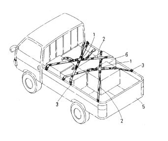
How to use the strap locking device is shown in Figure 10,
wherein the first, the second, the fifth or the sixth embodiment of the strap
locking device can be applied to bind freight 6 on a truck, depending on the
20 condition of the freight 6, with the hooks 3 at the outer ends of the
adjustable strap 2 or unadjustable strap 2' hooked on stationary hooks 51 of
the truck 5. Figure 11 shows how the third, the fourth, the seventh or the
eighth embodiments are applied to secure freight on a truck, with the hooks
of the adjustable strap 2 or the unadjustable strap 2' hooked on the hooks
25 51 of a truck.
While the preferred embodiments of the invention have been
described above, it will be recognized and understood that various
modifications may be made therein and the appended claims are intended to


.: .~

' 2~9745

cover all such modifications which may fall within the spirit and scope of the
invention.


,~

Dessin représentatif
Une figure unique qui représente un dessin illustrant l'invention.
États administratifs

Pour une meilleure compréhension de l'état de la demande ou brevet qui figure sur cette page, la rubrique Mise en garde , et les descriptions de Brevet , États administratifs , Taxes périodiques et Historique des paiements devraient être consultées.

États administratifs

Titre Date
Date de délivrance prévu 1999-06-01
(22) Dépôt 1993-11-23
Requête d'examen 1993-11-23
(41) Mise à la disponibilité du public 1995-05-24
Correction de la demande morte 1997-12-22
(45) Délivré 1999-06-01
Réputé périmé 2000-11-23

Historique d'abandonnement

Il n'y a pas d'historique d'abandonnement

Historique des paiements

Type de taxes Anniversaire Échéance Montant payé Date payée
Le dépôt d'une demande de brevet 0,00 $ 1993-11-23
Taxe de maintien en état - Demande - nouvelle loi 2 1995-11-23 50,00 $ 1995-11-23
Taxe de maintien en état - Demande - nouvelle loi 3 1996-11-25 50,00 $ 1996-11-12
Taxe de maintien en état - Demande - nouvelle loi 4 1997-11-24 50,00 $ 1997-11-14
Taxe de maintien en état - Demande - nouvelle loi 5 1998-11-23 75,00 $ 1998-11-23
Taxe finale 150,00 $ 1999-03-01
Titulaires au dossier

Les titulaires actuels et antérieures au dossier sont affichés en ordre alphabétique.

Titulaires actuels au dossier
CHOU, AN-CHUAN
Titulaires antérieures au dossier
S.O.
Les propriétaires antérieurs qui ne figurent pas dans la liste des « Propriétaires au dossier » apparaîtront dans d'autres documents au dossier.
Documents

Pour visionner les fichiers sélectionnés, entrer le code reCAPTCHA :


Pour visualiser une image, cliquer sur un lien dans la colonne description du document. Pour télécharger l'image (les images), cliquer l'une ou plusieurs cases à cocher dans la première colonne et ensuite cliquer sur le bouton "Télécharger sélection en format PDF (archive Zip)" ou le bouton "Télécharger sélection (en un fichier PDF fusionné)".

Liste des documents de brevet publiés et non publiés sur la BDBC .

Si vous avez des difficultés à accéder au contenu, veuillez communiquer avec le Centre de services à la clientèle au 1-866-997-1936, ou envoyer un courriel au Centre de service à la clientèle de l'OPIC.


Description du
Document 
Date
(yyyy-mm-dd) 
Nombre de pages   Taille de l'image (Ko) 
Page couverture 1995-07-14 1 16
Abrégé 1995-05-24 1 26
Description 1995-05-24 7 223
Revendications 1995-05-24 2 74
Dessins 1995-05-24 10 213
Abrégé 1998-08-26 1 21
Description 1998-08-26 6 204
Revendications 1998-08-26 3 104
Page couverture 1999-05-26 1 38
Dessins représentatifs 1999-05-26 1 12
Correspondance 1999-03-01 1 34
Correspondance de la poursuite 1996-09-01 2 47
Demande d'examen 1996-03-01 1 64
Taxes 1996-11-12 1 43
Taxes 1995-11-23 1 41