Sélection de la langue

Search

Sommaire du brevet 2114062 

Énoncé de désistement de responsabilité concernant l'information provenant de tiers

Une partie des informations de ce site Web a été fournie par des sources externes. Le gouvernement du Canada n'assume aucune responsabilité concernant la précision, l'actualité ou la fiabilité des informations fournies par les sources externes. Les utilisateurs qui désirent employer cette information devraient consulter directement la source des informations. Le contenu fourni par les sources externes n'est pas assujetti aux exigences sur les langues officielles, la protection des renseignements personnels et l'accessibilité.

Disponibilité de l'Abrégé et des Revendications

L'apparition de différences dans le texte et l'image des Revendications et de l'Abrégé dépend du moment auquel le document est publié. Les textes des Revendications et de l'Abrégé sont affichés :

  • lorsque la demande peut être examinée par le public;
  • lorsque le brevet est émis (délivrance).
(12) Brevet: (11) CA 2114062
(54) Titre français: ATTELAGE TELESCOPIQUE VERROUILLABLE
(54) Titre anglais: EXTENDABLE LATCHABLE DRAFT LINK
Statut: Réputé périmé
Données bibliographiques
(51) Classification internationale des brevets (CIB):
  • B60D 1/01 (2006.01)
  • A01B 59/06 (2006.01)
  • B60D 1/155 (2006.01)
  • B60D 1/40 (2006.01)
(72) Inventeurs :
  • BREMNER, RONALD DEAN (Etats-Unis d'Amérique)
(73) Titulaires :
  • DEERE & COMPANY (Etats-Unis d'Amérique)
(71) Demandeurs :
  • DEERE & COMPANY (Etats-Unis d'Amérique)
(74) Agent: BORDEN LADNER GERVAIS LLP
(74) Co-agent:
(45) Délivré: 1997-12-30
(22) Date de dépôt: 1994-01-24
(41) Mise à la disponibilité du public: 1994-07-28
Requête d'examen: 1994-01-24
Licence disponible: S.O.
(25) Langue des documents déposés: Anglais

Traité de coopération en matière de brevets (PCT): Non

(30) Données de priorité de la demande:
Numéro de la demande Pays / territoire Date
009,610 Etats-Unis d'Amérique 1993-01-27

Abrégés

Abrégé français

Assemblage de pièces de traction télescopique comportant un premier élément creux rattaché au tracteur et un deuxième élément relié à l'engin remorqué qui peut s'insérer par glissement dans un canal du premier élément. Une plaque est montée dans un logement contigu au canal. Cette plaque est en mesure de tourner d'une position de dégagement, pour laquelle cette plaque est entièrement située dans le logement, à une position de verrouillage, pour laquelle une partie au moins de la plaque dépasse dans le canal. Le deuxième élément comporte une encoche, une extrémité de cette encoche formant un épaulement susceptible de s'engager avec la plaque pour maintenir le deuxième élément en position rétractée jusqu'à ce que la plaque soit dégagée. Un ressort comprimé oblige la plaque à conserver sa position de verrouillage et un bouton, fixé à la plaque, permet à un opérateur de faire tourner la plaque en position de dégagement.


Abrégé anglais


A telescoping draft link assembly includes a hollow first
tractor-coupled link and a second implement-coupled link
slidably received by a channel in the first link. A pocket is
formed in the first link next to the channel. A plate is
pivotally mounted in the pocket and is pivotal from a release
position wherein the plate is entirely received in the pocket
to a locking position wherein at least a portion of the plate
projects into the channel. The second link has a notch formed
therein, an end of the notch forming a shoulder which is
engageable with the plate to releasably hold the second link
in the retracted position. A spring is biased to urge the
plate towards its locking position and a knob is attached to
the plate so that an operator may pivot the plate to a release
position.

Revendications

Note : Les revendications sont présentées dans la langue officielle dans laquelle elles ont été soumises.


THE EMBODIMENTS OF THE INVENTION IN WHICH AN EXCLUSIVE
PROPERTY OR PRIVILEGE IS CLAIMED ARE DEFINED AS FOLLOWS:
1. A telescoping link assembly having a hollow first
link, a second link slidably received by a channel in the
first link and latching means for releasably holding the
second link in a retracted position with respect to the first
link, wherein:
the first link has a pocket formed therein adjacent to
the channel;
a plate is mounted in the pocket, the plate being pivotal
from a release position wherein the plate is substantially
received in the pocket to a locking position wherein at least
a portion of the plate projects into the channel;
a resilient member is based to urge the plate towards its
locking position;
the second link has a shoulder surface formed therein,
the shoulder surface being engageable with the plate to
releasably hold the second link in the retracted position;
a bore extends through a wall of the first link, the bore
being aligned with a central portion of the pocket; and
a post is fixed to a central portion of the plate and is
loosely received by the bore, the post being engageable with
the wall of the second bore to limit pivoting of the plate.
2. The link assembly of claim 1, wherein:
an aft end of the plate is pivotally held in the pocket
between a surface of the second link and a surface of the
first link.
3. The link assembly of claim 1, wherein:
a pivot bore extends through a wall of the first link,
the pivot bore being aligned with one end of the pocket; and
a pivot pin is fixed to an end of the plate and is
rotatably received by the pivot bore.
4. The link assembly of claim 3, wherein:
the pivot bore and the pivot pin have vertically oriented
axes.
5. The link assembly of claim 1, wherein:
a manually operable knob is fixed to an end of the post
outside of the first link.
6. The link assembly of claim 1, wherein:

the bore has a diameter which is larger than a diameter
of the post.
7. The link assembly of claim 1, wherein:
a spring bore extends laterally through a wall of the
first link and into the pocket; and
the resilient member is mounted in the spring bore, one
end of the resilient member engaging the plate.
8. The link assembly of claim 1, wherein:
an upper pivot bore extends through an upper wall of the
first link, a lower pivot bore extends through a lower wall of
the first link, the pivot bores being aligned with one end of
the pocket;
an upper pivot pin is fixed to an end of the plate and is
rotatably received by the upper pivot bore; and
a lower pivot pin is fixed to an end of the plate and is
rotatably received by the lower pivot bore.
9. The link assembly of claim 1, wherein:
the second link has a notch formed therein, the notch
forming the rearward facing shoulder surface which is
engageable with the plate.
10. The link assembly of claim 1, wherein:
the shoulder surface faces substantially rearward.
11. The link assembly of claim 1, wherein:
the second link has a notch formed therein, the notch
forming a sideways and forwardly facing bottom surface which
is slanted with respect to a longitudinal axis of the second
link.
12. A telescoping link assembly having a hollow first
link, a second link slidably received by a channel in the
first link and latching means for releasably holding the
second link in a retracted position with respect to the first
link, wherein;
the first link has a pocket formed therein adjacent to
the channel;
a plate is mounted in the pocket, the plate being pivotal
from a release position wherein the plate is substantially
received in the pocket to a locking position wherein at least
a portion of the plate projects in the channel;


a resilient member is biased to urge the plate towards
its locking position;
the second link has a shoulder surface formed therein,
the shoulder surface being engageable with the plate to
releasably hold the second link in the retracted position;
a spring bore extends laterally through a wall of the
first link and into the pocket;
the resilient member is mounted in the spring bore, one
end of the resilient member engaging the plate; and
a blind bore extends into the plate, said one end of the
resilient member being received by the blind bore.
13. A telescoping link assembly having a hollow first
link, a second link slidably received by a channel in the
first link and latching means for releasably holding the
second link in a retracted position with respect to the first
link, wherein:
the first link has a pocket formed therein adjacent to
the channel;
a plate is mounted in the pocket, the plate being pivotal
from a release position wherein the plate is substantially
received in the pocket to a locking position wherein at least
a portion of the plate projects into the channel;
a resilient member is biased to urge the plate towards
its locking position;
the second link has a shoulder surface formed therein,
the shoulder surface being engageable with the plate to
releasably hold the second link in the retracted position;
a spring bore extends laterally through a wall of the
first link and into the pocket;
the resilient member is mounted in the spring bore, one
end of the resilient member engaging the plate;
an outer portion of the spring bore is threaded; and
a screw is threaded into said outer portion to retain the
resilient member in the spring bore.

Description

Note : Les descriptions sont présentées dans la langue officielle dans laquelle elles ont été soumises.

S 2
EXTENDABLE LATCHABLE DRAFT LINK
Backqround of the Invention
The invention relates to a latchable telescoping draft
link assembly.
A known telescopic draft link assembly available with
John Deere tractors includes an implement coupling link which
slides inside a channel in another link which is coupled to
the tractor. The implement link is latched or held in place
by a cylindrical pin which is biased by a spring into
corresponding bores in the links. Such an assembly must be
accurately mach;ne~ to function properly. Also, the latch pin
is subjected to shear or tensile forces and may "freeze up".
Another known telescopic draft link assembly includes a part
that falls into a slot in the draft link end by gravity. Such
an assembly must also be accurately machined to function
properly, especially if the parts are forged. It would be
desirable to have a telescopic draft link assembly which is
simple to machine.
Summary of the Invention
Accordingly, an object of this invention is to provide a
telescopic draft link assembly which is simple to machine.
Another object of thi6 invention is to provide such a
dra~t link assembly with a latch mechanism which is not
subjected to 6hear or tensile forces.
Another ob~ect o~ this invention is to provide such a
draft link assembly with a latch mech~nism which is unlikely
to "freeze up".
Another ob~ect of this invention is to provide 6uch a
dra~t link assembly wherein the left and right components can
be made ~rom the same forgings.
These and other objects are achieved by the present
invention, wherein a telescoping draft link aesembly includes
a hollow tracto~-mounted link and an implement-coupling link
61idably received by a channel in the tractor-mounted link. A
pocket i~ formed in the tractor-mounted link next to the
channel. A plate iB pivotally mounted in the pocket and i~
pivotal from a release position wherein the plate is entirely
received in the pocket to a locking position wherein at least
a portion of the plate projects into the channel. The


~,~s
.

, ' ' .. ' ~' ': :,

2~14~)6~
implement-coupling link has a notch formed therein. An end of
the notch forms a shoulder which is engageable with the plate
to releasably hold the implement-coupling link in a retracted
position. A spring is biased to urge the plate towards its
locking position and a knob is attached to the plate so that
an operator may pivot the plate to a release position.
Brief Description of the Drawinqs
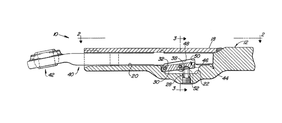
Fig. 1 is a partial sectional top view of a telescoping
draft link assembly constructed according to the present
lo invention;
Fig. 2 is view in the direction of arrows 2-2 of Fig. 1,
with portions removed for clarity;
Fig. 3 is a view taken along lines 3-3 of Fig. l;
Fig. 4 is perspective view of the implement-coupling link
portion of the present invention; and
Fig. 5 is a view similar to Fig. 2, but showing an
alternate preferred embodiment of the present invention.
Detailed Description
Referring to Figs. 1-3, a telescoping draft link assembly
10 includes a hollow first link 12 for coupling to a tractor
(not shown). The aft end portion of link 12 is substantially
U-shaped, with upper wall 14 and lower wall 16, as best seen
in Fig. 3. A plate 18 is welded to the walls 14,16 to enclose
a chAnnel 20. A forged pocket 22 is also formed in the fir~t
link 12. The pocket 22 is open to and adjacent to the forward
end of the ~h~nnsl 20. A pair of pivot bores 24 and 25 extend
vertically through the walls 14 and 16 and are aligned with
the aft end of pocket 22. A ~econ~ set of bores 26 and 27
extend vertlcally through the walls 14 and 16 and are aligned
with the central portion of pocket 22. A spring bore 28
extends horizontally through a side of link 12 and into pocket
22. '
A generally rectangular latching plate 30 i5 mounted in
the pocket 22. A pair oP pivot pin~ 32 and 33 are press fit
into corre~ponding bores in the top and bottom surfaces of the
plate 30 near its aft end. The pins 32 and 33 are rotatably
received in the pivot bores 24 and 25. A pair of posts 34 and

211~'~52
.
35 are press fit into corresponding bores near the center of
the top and bottom surfaces of the plate 30. The posts 34 and
35 are received in the bores 26 and 27. The diameter of bores
26 and 27 are larger than the diameter of the posts 34 and 35
and the free-play therebetween permits the plate 30 to pivot
about the axis of pins 32 and 33 between a latching position
and a release position. A knob 36 is attached to the end of
post 34 outside of wall 14 so that an operator can manipulate
the plate 30 as desired. A blind bore 38 extends horizontally
part way into the side of plate 30. It should be note that
the lower post 35 and bore 27 could be eliminated because pins
32 and 33 and bores 26 and 27 will be sufficient to maintain
proper orientation of the plate 30 in the pocket 22.
As best seen in Fig. 4, a second link 40 has an aft end
42 for coupling to an implement (not shown) and a forward end
44 which is received by the chAnnel 20. A notch 46 is formed
on one side o~ link 40 near, but spaced apart from, its
forward end. The notch 46 has a surface 48 which is slanted
with respect a longitud~nAl axis of the link 40, which faces
generally to the ~ide and slightly forwardly, and which is
joined to shoulder surface 50.
A coil spring 52 is mounted in spring bore 28 and is held
in place by a screw 54 which is S~L ewed into a threaded outer
portion of spring bore 28. The inner end of spring 52 i8
received by bore 38 in plate 30. The spring 52 i5 biased to
pivot plate 30 about the axis of pivot pins 32 and 33 and to
urge the ~orward end of the plate 30 out of the pocket 22 and
into the c-h~nnel 20.
Referring now to Fig. 5, there is shown a preferred
embodiment which i8 ~imilar to the embodiment of Figs. 1-4,
except that the pivot bores 24 and 25 and the pivot pins 32
and 33 are eliminated. In this case, the a~t end o~ the plate
30 would be pivotally held in place in the pocket 22 between
the link 12 and the ~ur~ace o~ the link 40. Also, when the
link 40 i~ removed ~rom link 12, the spring 52 and the
engagement between post~ 34, 35 and bores 26, 27 will tend to


.
: ,, ". , ' ' " , . ,

2~ a6~
hold the aft end of plate 30 in the position illustrated in
Fig. 1.
As the link 40 is moved to right (viewing Fig. 1~ into
channel 20, the forward end of link 40 will engage plate 30
and push plate 30 into pocket 22 against the force of spring
52. Then, when notch 46 is adjacent to pocket 22 as shown in
Fig. 1, the spring 52 automatically pivots plate 30 to a
locking position wherein the end of the plate 30 projects into
the notch 46. In this locking position, the forward end of
plate 30 will engage the shoulder surface 50 and prevent
inadvertent withdrawal of link 40 from channel 20. The plate
30 may be manually pivoted out of notch 46 by pushing on the
knob 36, whereupon the link 14 may be removed or extended from
the channel 20.
With this design the same parts can be used on the left
and right sides of the tractor hitch ~not shown). The latch
plate 30 is sub~ected to compression forces only, and so is
not sub~ect to shear or tensile forces. The latch plate 30 is
unlikely to "freezes up" as does the latch mechanism of
alternate designs. If the pivot bores 24 and 25 and the pivot
pins 32 and 33 are used, then only bores 24 and 25 need to be
accurately machined into the link 12. Tolerances are not
critical.
While the present invention has been described in
con~unction with a specific embodiment, it is understood that
many alternatives, modifications and variations will be
apparent to those skilled in the art in light of the foregoing
description. Accordingly, this invention is intended to
embrace all such alternatives, modifications and variations
which fall within the spirit and scope of the appended claims.


",:
'','
. . ..
: . ": ' , ,

Dessin représentatif
Une figure unique qui représente un dessin illustrant l'invention.
États administratifs

Pour une meilleure compréhension de l'état de la demande ou brevet qui figure sur cette page, la rubrique Mise en garde , et les descriptions de Brevet , États administratifs , Taxes périodiques et Historique des paiements devraient être consultées.

États administratifs

Titre Date
Date de délivrance prévu 1997-12-30
(22) Dépôt 1994-01-24
Requête d'examen 1994-01-24
(41) Mise à la disponibilité du public 1994-07-28
(45) Délivré 1997-12-30
Réputé périmé 2005-01-24

Historique d'abandonnement

Il n'y a pas d'historique d'abandonnement

Historique des paiements

Type de taxes Anniversaire Échéance Montant payé Date payée
Le dépôt d'une demande de brevet 0,00 $ 1994-01-24
Enregistrement de documents 0,00 $ 1994-07-29
Taxe de maintien en état - Demande - nouvelle loi 2 1996-01-24 100,00 $ 1996-01-23
Taxe de maintien en état - Demande - nouvelle loi 3 1997-01-24 100,00 $ 1997-01-23
Taxe finale 300,00 $ 1997-09-10
Taxe de maintien en état - brevet - nouvelle loi 4 1998-01-26 100,00 $ 1998-01-23
Taxe de maintien en état - brevet - nouvelle loi 5 1999-01-25 150,00 $ 1999-01-22
Taxe de maintien en état - brevet - nouvelle loi 6 2000-01-24 150,00 $ 2000-01-21
Taxe de maintien en état - brevet - nouvelle loi 7 2001-01-24 150,00 $ 2001-01-23
Taxe de maintien en état - brevet - nouvelle loi 8 2002-01-24 150,00 $ 2002-01-23
Taxe de maintien en état - brevet - nouvelle loi 9 2003-01-24 150,00 $ 2003-01-23
Titulaires au dossier

Les titulaires actuels et antérieures au dossier sont affichés en ordre alphabétique.

Titulaires actuels au dossier
DEERE & COMPANY
Titulaires antérieures au dossier
BREMNER, RONALD DEAN
Les propriétaires antérieurs qui ne figurent pas dans la liste des « Propriétaires au dossier » apparaîtront dans d'autres documents au dossier.
Documents

Pour visionner les fichiers sélectionnés, entrer le code reCAPTCHA :


Pour visualiser une image, cliquer sur un lien dans la colonne description du document. Pour télécharger l'image (les images), cliquer l'une ou plusieurs cases à cocher dans la première colonne et ensuite cliquer sur le bouton "Télécharger sélection en format PDF (archive Zip)" ou le bouton "Télécharger sélection (en un fichier PDF fusionné)".

Liste des documents de brevet publiés et non publiés sur la BDBC .

Si vous avez des difficultés à accéder au contenu, veuillez communiquer avec le Centre de services à la clientèle au 1-866-997-1936, ou envoyer un courriel au Centre de service à la clientèle de l'OPIC.


Description du
Document 
Date
(yyyy-mm-dd) 
Nombre de pages   Taille de l'image (Ko) 
Revendications 1997-04-22 3 140
Page couverture 1995-06-10 1 24
Abrégé 1995-06-10 1 25
Revendications 1995-06-10 3 137
Dessins 1995-06-10 2 61
Description 1995-06-10 4 196
Page couverture 1997-12-16 1 54
Dessins représentatifs 1997-12-16 1 11
Correspondance de la poursuite 1994-06-05 2 44
Correspondance de la poursuite 1994-09-06 1 19
Correspondance reliée au PCT 1997-09-10 1 31
Taxes 1997-01-23 1 56
Taxes 1996-01-23 1 32