Sélection de la langue

Search

Sommaire du brevet 2114868 

Énoncé de désistement de responsabilité concernant l'information provenant de tiers

Une partie des informations de ce site Web a été fournie par des sources externes. Le gouvernement du Canada n'assume aucune responsabilité concernant la précision, l'actualité ou la fiabilité des informations fournies par les sources externes. Les utilisateurs qui désirent employer cette information devraient consulter directement la source des informations. Le contenu fourni par les sources externes n'est pas assujetti aux exigences sur les langues officielles, la protection des renseignements personnels et l'accessibilité.

Disponibilité de l'Abrégé et des Revendications

L'apparition de différences dans le texte et l'image des Revendications et de l'Abrégé dépend du moment auquel le document est publié. Les textes des Revendications et de l'Abrégé sont affichés :

  • lorsque la demande peut être examinée par le public;
  • lorsque le brevet est émis (délivrance).
(12) Brevet: (11) CA 2114868
(54) Titre français: DISPOSITIF DE PRISE EN CHARGE DE SIGNAUX DE CONFERENCE COMPRIMES
(54) Titre anglais: CONFERENCING ARRANGEMENT FOR COMPRESSED INFORMATION SIGNALS
Statut: Réputé périmé
Données bibliographiques
(51) Classification internationale des brevets (CIB):
  • H04M 3/56 (2006.01)
(72) Inventeurs :
  • NAHUMI, DROR (Etats-Unis d'Amérique)
(73) Titulaires :
  • AMERICAN TELEPHONE AND TELEGRAPH COMPANY (Etats-Unis d'Amérique)
(71) Demandeurs :
(74) Agent: KIRBY EADES GALE BAKER
(74) Co-agent:
(45) Délivré: 1997-12-23
(22) Date de dépôt: 1994-02-03
(41) Mise à la disponibilité du public: 1994-09-25
Requête d'examen: 1994-02-03
Licence disponible: S.O.
(25) Langue des documents déposés: Anglais

Traité de coopération en matière de brevets (PCT): Non

(30) Données de priorité de la demande:
Numéro de la demande Pays / territoire Date
036,588 Etats-Unis d'Amérique 1993-03-24

Abrégés

Abrégé français

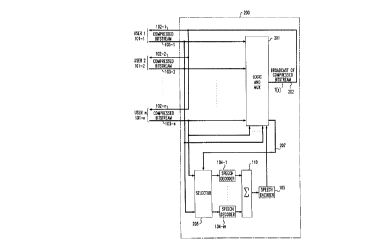
Technique de pont de conférence pour les signaux compressés d'information qui surveille l'énergie des signaux transmise par chaque participant. Si seulement un participant parle, le circuit de sommation du pont est contourné ainsi que l'appareil de codage/décodage des signaux vocaux et le signal du participant qui parle est diffusé à tous les participants. S'il y a plus d'un participant qui parle à un moment donné, alors seulement les signaux vocaux d'un des participants sont acheminés vers un décodeur correspondant de signaux vocaux où les signaux compressés du participant sont décompressés. Ces signaux compressés sont ensuite combinés par le circuit de sommation et la somme est compressée de nouveau et diffusée à tous les participants. Avantageusement, la technique décrite ci-dessus élimine la dégradation de signaux correspondant à la mise en tandem d'opérations de codage et de décodage de signaux et permet le partage d'un plus petit nombre de décodeurs entre un plus grand nombre de participants.


Abrégé anglais


-8-

A conferencing bridging technique for compressed information signals
which monitors the signal energy transmitted by each conferee. When there is only
one conferee speaking, the summing circuit in the bridge unit is bypassed along with
the speech decoding/coding apparatus and the talking conferee's signal is broadcast
to all conferees. If there is more than one conferee speaking at any given time, then
only the speaking conferee's signals are routed to an associated speech decoder
wherein those conferees' compressed signals are decompressed. These
decompressed signals are then combined by the summing circuit and the sum is
recompressed and broadcast to all conferees. Advantageously, the above-describedtechnique eliminates the signal degradation associated with tandeming of signal
decoding and coding operations and permits the sharing of a smaller number of
signal decoders among a larger number of conferees.

Revendications

Note : Les revendications sont présentées dans la langue officielle dans laquelle elles ont été soumises.


- 5 -

Claims:
1. Apparatus for providing conferencing communications comprising
means for combining signals from at least three input communications
paths onto an output communications path;
means for monitoring the signal energy in each of the input
communications paths; and
means responsive to the signal energy monitoring for bypassing said
combining means and coupling the signal on one of the input communications pathsonto the output communications path when said signal energy monitoring provides a
first result.

2. The apparatus of claim 1 wherein said first result is that the signal
energy monitored is above a predetermined threshold on only one of the input
communications paths.

3. The apparatus of claim 2 wherein the one signal bypassing said
combining means and being coupled onto the output communications path is that
signal whose signal energy exceeds said predetermined threshold.

4. The apparatus of claim 3 wherein said predetermined threshold
corresponds to the signal energy present typically associated with a person speaking.

5. The apparatus of claim 1 further including means responsive to a
second result of the signal energy monitoring for coupling the signal on each of a
subset of the communications paths to a corresponding signal decoder and thence to
said combining means.

6. The apparatus of claim 5 wherein said subset includes only those
communications paths whose associated signal energy exceeds a predetermined
threshold.

7. The apparatus of claim 5 wherein said coupling means includes a
demultiplexer.

8. The apparatus of claim 1 wherein any signal on the input
communications paths includes a sequence of compressed digital signal samples and


- 6 -

said combining means includes means for decompressing compressed digital signal
samples on certain ones of the input communications paths.

9. The apparatus of claim 8 wherein the certain ones of the input
communications paths varies with time.

10. The apparatus of claim 8 wherein the certain ones of the input
communications paths are determined by said signal energy monitoring means.

11. The apparatus of claim 10 wherein the certain ones of the
communications paths are those determined by said signal energy monitoring means to
be communicating a signal having an associated signal energy level greater than a
predetermined threshold.

12. A method for providing conferencing communications comprising
combining signals from at least three input communications paths onto an
output communications path;
monitoring the signal energy in each of the input communications paths; and
bypassing said combining means and coupling one of the signals onto the
output communications path when the signal energy monitoring step provides a first
result.

13. Apparatus comprising
means for monitoring the level of signal energy that may be present on each
of at least three communications paths and identifying those of said paths having signal
energy levels exceeding a predetermined threshold, the presence of signal energy on
any of said paths being indicative of compressed signals on that path, and
means for decompressing the signals on each of the identified paths.

14. The apparatus of claim 13 further including a signal combiner connected
to said decompressing means.


- 7 -

15. The apparatus of claim 13 further including means for bypassing said
signal combiner and said decompressing means when said monitoring means identifies
only one path.

16. A method comprising the steps of
monitoring the level of signal energy that may be present on each of at least
three communications paths and identifying those of said paths having signal energy
levels exceeding a predetermined threshold, the presence of signal energy on any of
said paths being indicative of compressed signals on that path, and
decompressing the signals on each of the identified paths.

Description

Note : Les descriptions sont présentées dans la langue officielle dans laquelle elles ont été soumises.


-- 2 ~ 6 ~
.

1 -
CONFERENCING ARRANGEMENT FOR COMPRESSED
INFORMATION SIGNALS

Technical Field
The present invention relates to a t~ chl~iq~c for plUviding C~.re -,nCing
S c~a~ -lity and, more particularly, to a te~hni~ for providing this c~?ahility when
the signals to be conf~ nced are com~ sed.
Back~roundofthe 1 ~
C,..r~rf ncing is the ~ p~ ' ~lity of co~pli~-g illrO....~io~- signals among
three or more users in a co~...~ ir ~ system The ;..rn. ,...1~in.~ signals are
10 typically voice signals but, with the advent of mll1time~ c~
kiliti~s~ can also be ~ ~ ice signa1s, i.e., data, video, f~c~;rnil~ and the like.
Sigral colllple~s;on te~hniques have long been used to reduce the
~z ~d~.;.llll required for signal tr~ ;m~ These ti c~ f have been used for
both voice and data signals.
When colll~ s~d inforrnation signals are confel.,nced using existing ~ -
,ncebridgingi~'~ s thecolll~ scdsignalsareeach ~leCn~ Sscd~ .
summed and this sum is then ,~co""~lessed and blu~dca~ tO all col.r~,l~s. The
with this ~ uach is that the t~ f 1~ ae~ i.e., serial conn~cti(!n of signal
coders and ckco~ to I~ l), COIl~ SS and dccûlll~Jrf~sS the ;..rO,.,, ~';on
20 signal, degrades the res~11ting signal quality to a level that, in trial studies, has been
found to be obJe cti~ ~a~'~ to many conr~,l~s. Another problem is that dhe bridging
apparatus can be cosdy, eq~eciq11y for cc r _ _ bridging apparatus capable of
g a large number of co~f~,- 5;e s At tirnes, the signal dc~ and/or
the apparatus costs associated with to..fclbnc~g c~ "~ can exceed system
25 obJ~,cli~es. At such times, the prior art solution has been to utilize only
u ~ fbss~d signals. This so1uti~n, in turn, requires a higher bandwidth
co~l....---.:-~dtions channel between any pc~ ' conferee and the conÇ~,lGncing
apparatus. This l~ui,~ ,nl can be ~.~115;~, or difficult to provide. This is
especi~11y true in c - ~ ~ system appli nn~ where the number of po:
30 conre~ie~s is quite large. It would, ~ ,fule, be dPSir~ if a conrclbl.~ing
at~---.g~ 1 could be devised for con~p~ ,sed signals which o .el~;ull,es the
c of the prior art.
~ '' -' '' ' '.' "


'
......

8 ~ 8

-2-
Summary of the Invention
The present invention relates to a confcr~n~ g atl lg~.ment for
c~~ e;,sed ~ signals. ~ to the present invention, when there is
only one confe.~ ~r ~ r~ ~ g~ the summer in the ~ c r ~nce bridge is b,~r d and
5 that co~ fcl~e's signal is broad~&i.l to all - - f~ ~s. If, on the other hand, there is
more than one ~ - ~ e -~ - ' ~ C, the signals of only those COnff l't~S who are
speaking are routed to an r-so - - I speech decoder. The clcco..~ ,d speech
signals outputted by each decoder are then summed and this sum is c~ s~ed
again and l~ to all of the ~c ~ rees The above-descrihed technique
10 advan:ae ~ cly reduces the signal deg~ :~ ~r '~~Q~- d with the tandeming of
signal coders and d~co~c- ~ and permits the sharing of a smaller number of signal
de~le- ~ among a larger number of ~ - r e
Brief Dcscription of the Drawin~
FIG. 1 is a block-s ' ~ r diagram of a prior art confc.~nce bridge ~ -
15 unit; and -~
FIG. 2 is a block-sc~ diagram of a conf,~nce bridge unit in
P~C~ ' --e withthepresentin~_nlion.
Detailed Description
Prior art bridge 100, shown in FIG. 1, plo.id~s ill ls_ voice
20 c c r ~ ~ sing communications e ~a~ ' ~y for n users, where n is a pl~l~ ~ - .. ;ned - -
integer greater than 2. Each of the n users is c c - - - c ~Pd to the c - Ff r~ bridge via
one of n two-wire comm ~ ~ -- paths 101-1 through 101-n. Each of these paths
includes an incoming lead 102 and an outgoing lead 103. Summer 110 in the bridgeunit is r ~ ~ ~e ' d to each incoming lead 102 and p~-W~s an output signal, T(z), to
25 each~ lead103. Forpurposesofil' ~ ,itshallbea~ ~thatthe
summer ~ .i~S unity gain and no loss is i~ h~d by the bridge unit. The output
signal T(z) is therefore equal to the sum of the signals on all n ~ - - ~ g leads 102.
This output signal is coupled to each of the n users and is pnJcess~ using well-known techniques so that each user hears the speech of any of the n-l other users.
In the illustradve circuitry of FIG. 1 the signals coupled to and from the
conference bridge are colll~ ;Jsed signal samples. As a result, the c~ r ~,nce bridge
unit includes speech dccod~.~ 104-1 through 104-n to ~leco~ ,ss the speech signals
in each of the n incoming leads. The output signal ~Iu.i~d by each speech decoder
can be either an L r ~ , es~cd digital signal or an analog signal. In any event, the
35 decoding functdon is needed to form the signal sum. After s~mm;ng the

8 ~ ~
- 3 -
dec-J..~l..ei,svd signals must be CO~ b~ied prior to being l~oddcasl to all users.
Speech encoder 105 provides this function.
Refer now to FIG. 2 which shows an illuatldli~v c-.~ f ~l of the
presentinvention. Too~_l.;ulllethesignalde6~ ~ ?~soçi!~tedwiththe
l~ g of several colll~lv~ul~/d~co~l~lv~ vOnrv vnCv bridge unit 200
illCvl~Jul~tvs logic circuit 201. Circuit 201 includes well-known signal energyd~ t~;l;ol) app ~ .c which lllol-ilul~ the signal energy in each of the intoming leads.
With the available signal co ll~.v;,sion ~ this function can be provided
without co , le~ ,~y decovliilg any of the colll~.vss-vd bil ~heams. That is, the signal~0 energy present in each of the ~ - - ming leads can be df t~ . ."inr~l by directly
g the co.l~ -vi,~d bitstream in that lead or by .... l.;l.,. ;.-g a partially
decoded version of this bit~llea..l. The latter is, of course, generally ~e~ as it
avoids the need for a decoder in each of the inc~J...;~-g leads.
When there is energy present in only one lead, i~dir~ g only one
talking conferee, this conferee's cc~ vi,~vd signal is broadcast to all confv.cvs via
lead 202 without passing the speevh decoder and coder and without passing through
summer 110. If, Ih~ _r, there is more than one talking conferee at a given time, ~ -
then only those confc.ves' signals are coupled to speech decodf ~ The talking
co. r~,.~S, i.e., the il'COming lines on which signal energy above a plCd~ te- ...;~
20 threshold is present, are i~l~ntifiPd by logic circuit 201 and these i~-~o..~ .-g Iead
identifications are provided to selector 203 via lead 207. Selector 203is coupled to
each of the n ill.~o...~ leads and, in ~b~)nSc, to the i~1Pn~ifi~ nn signal on lead 207,
couples each of the i~1pntifipd ~ ' g leads to a dirf~cnt one of speech
cle~odf--~ 104-1 through 104-m. These speech dccod~.~ are i~lPnti-~l to those inFIG.1. IIo.._~ cco~ e that only the spe?lcing conrf,~s' signals must be
dec... 'l"5 ~sed and the number of conrf,l~s speaking at the same time is generally
one or, at worse, a small subset of the total number of cOI~r~.ces~ the bridge unit can
be configllred with fewer d~od~ than the ...~ .. number of cO.,r~.ccS.
Therefore, the integer m is less than n by some plc-l. t~,- ...i~-fd amount and the
30 decod,~ in FIG. 2 are eff~li~_ly shared between the confcl~,f,s as needed. This use
of m dccod~ instead of n deco~.~ does not degrade system p~ l f~ - e if it is
~oen; 1~1 that when the number of spe ~l~in~ conÇe.~s at any time is s fl,~talltially
more than one, the i,-rc,. ll~ ~inn is probably Imin~ igihle. Accepting this concl~ n~
a co..rf~ e bridge in accold ~e with the present invention can utilize far fewer35 ~3~od~ than the ...~ .. number of conre.cf,s at any time.

. .

8 ~ 8
- 4 -
Each of the CO.~ ssad speech signals coupled through selector 203 is
deco..~ es~d by its ~sc- ~ speech decoder and summer by summer 110. The
sum thus formed is then co~ ~s~d by speech encoder 105 before being blO~Cd~
to all e ~ r ~S in the same manner as in FIG. 1.
It should, of course, be noted that while the present hl- - - has been
s~ihed in terms of an ill~ dli~_ elllb~ , other ~ g - will be
apparent to those of ordinary skill in the art. For e , ' e, while the present
has been ~le s~ . ;hcd reladve to the c - r ~ ~ lg of Cjlll~ sed digital
signa1s l-r ~ of speech, the present hl~ ion is a~ le to the p~cc~ g
10 of CO~ J-~C1 digital signals regardless of the r~ - ~ ~ represented by such
signals. Second, while in the f~ osed e-.. ho~ nt there is no echo cancellation or ~ -
su~ ~ Dr apparatus p.~.idcd in the conferencing a~g. -..~ --l, the present
~ can ~ ~ such apparatus. Third, while in the ~ osod e-.-~;-..~
one conf~ - - 2 bridge 200 is utilized, in other co.,f~ g ~ I..agf .". -.t~ a plurality
15 of co.lfi,~ - bridges ~ - . - : ~ to each other may be utilized. Finally, while -
the d; 1~se~ 3- utilizes discrete devices, these devices can be
usingoneormore ~r .r - ~ dg_n~ purpose
~,l~e ss~ , r special-purpose integrated circuits, r digital pl~ce ~ > or an analog ~ -
or hybrid c rp~rt of any of these devices.


';


Dessin représentatif
Une figure unique qui représente un dessin illustrant l'invention.
États administratifs

Pour une meilleure compréhension de l'état de la demande ou brevet qui figure sur cette page, la rubrique Mise en garde , et les descriptions de Brevet , États administratifs , Taxes périodiques et Historique des paiements devraient être consultées.

États administratifs

Titre Date
Date de délivrance prévu 1997-12-23
(22) Dépôt 1994-02-03
Requête d'examen 1994-02-03
(41) Mise à la disponibilité du public 1994-09-25
(45) Délivré 1997-12-23
Réputé périmé 2009-02-03

Historique d'abandonnement

Il n'y a pas d'historique d'abandonnement

Historique des paiements

Type de taxes Anniversaire Échéance Montant payé Date payée
Le dépôt d'une demande de brevet 0,00 $ 1994-02-03
Enregistrement de documents 0,00 $ 1994-07-29
Taxe de maintien en état - Demande - nouvelle loi 2 1996-02-05 100,00 $ 1996-01-22
Taxe de maintien en état - Demande - nouvelle loi 3 1997-02-03 100,00 $ 1997-01-09
Taxe finale 300,00 $ 1997-09-12
Taxe de maintien en état - brevet - nouvelle loi 4 1998-02-03 100,00 $ 1998-01-06
Taxe de maintien en état - brevet - nouvelle loi 5 1999-02-03 150,00 $ 1998-12-21
Taxe de maintien en état - brevet - nouvelle loi 6 2000-02-03 150,00 $ 1999-12-20
Taxe de maintien en état - brevet - nouvelle loi 7 2001-02-05 150,00 $ 2000-12-14
Taxe de maintien en état - brevet - nouvelle loi 8 2002-02-04 150,00 $ 2001-12-20
Taxe de maintien en état - brevet - nouvelle loi 9 2003-02-03 150,00 $ 2002-12-18
Taxe de maintien en état - brevet - nouvelle loi 10 2004-02-03 250,00 $ 2003-12-19
Taxe de maintien en état - brevet - nouvelle loi 11 2005-02-03 250,00 $ 2005-01-06
Taxe de maintien en état - brevet - nouvelle loi 12 2006-02-03 250,00 $ 2006-01-05
Taxe de maintien en état - brevet - nouvelle loi 13 2007-02-05 250,00 $ 2007-01-08
Titulaires au dossier

Les titulaires actuels et antérieures au dossier sont affichés en ordre alphabétique.

Titulaires actuels au dossier
AMERICAN TELEPHONE AND TELEGRAPH COMPANY
Titulaires antérieures au dossier
NAHUMI, DROR
Les propriétaires antérieurs qui ne figurent pas dans la liste des « Propriétaires au dossier » apparaîtront dans d'autres documents au dossier.
Documents

Pour visionner les fichiers sélectionnés, entrer le code reCAPTCHA :


Pour visualiser une image, cliquer sur un lien dans la colonne description du document. Pour télécharger l'image (les images), cliquer l'une ou plusieurs cases à cocher dans la première colonne et ensuite cliquer sur le bouton "Télécharger sélection en format PDF (archive Zip)" ou le bouton "Télécharger sélection (en un fichier PDF fusionné)".

Liste des documents de brevet publiés et non publiés sur la BDBC .

Si vous avez des difficultés à accéder au contenu, veuillez communiquer avec le Centre de services à la clientèle au 1-866-997-1936, ou envoyer un courriel au Centre de service à la clientèle de l'OPIC.


Description du
Document 
Date
(yyyy-mm-dd) 
Nombre de pages   Taille de l'image (Ko) 
Page couverture 1997-12-16 1 58
Abrégé 1995-03-18 1 45
Page couverture 1995-03-18 1 42
Revendications 1995-03-18 3 170
Dessins 1995-03-18 2 69
Description 1995-03-18 4 266
Revendications 1997-03-25 3 95
Dessins représentatifs 1997-12-16 1 6
Revendications 1998-08-24 3 95
Correspondance de la poursuite 1994-02-03 5 200
Correspondance reliée aux formalités 1997-09-12 1 53
Correspondance de la poursuite 1997-01-27 2 67
Demande d'examen 1996-11-08 2 57
Taxes 1997-01-09 1 159
Taxes 1996-01-22 1 130