Note : Les descriptions sont présentées dans la langue officielle dans laquelle elles ont été soumises.
2 ~ 11 4 9 9 ~
A PRESSURE-REDUCING REGULATOR
FOR COMPRESSED NATLRAL GAS
Background of the Invention
This invention pertains to regulators for safely reducing high pressure natural
gas to pressure levels which are usable in vehicular engines. There is a need
for A~t~ob~le m~kers to provide an alternative fuels ~A~A~ility in a percentage
o~ their vehicles in this decade. Concc~itantly, then, there is a need for a
pressure-reducing regulator which can acc ~ o~te the high pressure natural gas,
which is stored in veh;culAr storage tanks, and reduce it down to usable pressure
levels, to facilitate the production of the alternative fuels automobiles.
majority of pressuIe-reducing regluators for c~,~Lessed natural gas, as are known
in the prior art, lack a balanced valve design. Accordingly, the output pressure
can ~ uct~lAte wldely, as the using vehicle consumes the fuel. To overcome thisdrawback, typically two of such reguiators are ~mployed to provide an acceptablere~-lAticn. Exemplary of this type of regulator is the Type P NGV Regulator, orthe Type P NGV Regulator with Enviro-Cap, manufactured and soldby Mbdern Enginee -
ing Company, Inc. of Ç~llmAn~ Mississippi. O~her prior art regulators use pistcns
to sense and track the outlet pressure and csntrol the regulator. Such pistons,t~hich carries seals, usually O-rings, manifest a response lag arising from the
fr~ct~orPl drag of the seals. Regulators of this latter type are offered by theTescom Corporatian.
Patent Nb. 3,712,333, issued to Albert L. Semcn, on January 23, 1973, for a Fluid
Pressure Com~c~ti~g Regulator, sets forth a valving element of square cross
sectl~n, which requires that the corners of the same slidably and frictionally
tranclate thrcugh a housing. Too, it has a diaphragm-carried insertwhich, t~henthe A~Arhr~gm bottcms, has no gas flow ~Cc~ f~tit~n provided therein.
It is a puspose of this inventi~n to set forth a pressure-r ~ ~ng rP~ tor
which, by itself, is usable in vehicular applic~tionc, and is of efficient and
~ pllcAted str~cture, the same having a balanced valving elP~Pnr d~L~ ~ nt
which has n~ n~ m~l frictional drag.
~ '149~
Summary of the Inventlon
Accordlng to a first broad aspect, the lnventlon
provldes a pressure-reduclng regulator for compressed natural
gas, comprlslng a regulator body; sald body havlng (a~ an
inner chamber for recelvlng hlgh-pressure gas thereln, and (b)
an outer chamber for dlscharglng low-pressure gas therefrom;
portlng means, formed ln sald body, for admlttlng gas lnto
sald lnner chamber, and for dlscharglng gas from sald outer
chamber; and valvlng means, wlthln sald body, for controlllng
fluld communlcatlon between sald chambers; whereln sald lnner
chamber and sald valving means have structural means whlch
cooperatlvely deflne (a) a seatlng area, and (b) a sealing
area for said valving means; both said areas comprise means
for definlng boundarles between dlfferentlal pressures of
lnner chamber hlgh-pressure gas and outer chamber low-pressure
gas; and sald valvlng means comprlses means for (a) equallzlng
magnltudes of forces of such differential pressures, (b)
dlrectlng such forces ln balanced opposltlon, ln said areas,
and (c) malntalnlng equallzation of such forces and
opposltely-dlrected balancing thereof, in said areas,
regardless of how pressures of such lnner chamber high-
pressure gas and such outer chamber low-pressure gas vary.
Preferably, said body further has means for
lnhlbiting an icing of said regulator, said lnhlbltlng means
comprlslng means for enveloping at least said inner chamber
and said valvlng means with a heating medium. In this, said
enveloping means comprises means for (a) pooling a heating
medium therein, and (b) admitting and discharging such heating
-- 2
72432-80
~;
4 9 ~ ~
medlum thereto and therefrom.
Accordlng to a second broad aspect, the lnventlon
provides a pressure-reducing regulator for compressed natural
gas, comprlslng a regulator body; sald body havlng (a) an
lnner chamber for receivlng high-pressure gas therein, and (b)
an outer chamber for dlscharglng low-pressure gas therefrom;
and a diaphragm flxed ln sald body; whereln said dlaphragm
comprlses a wall of sald outer chamber; and portlng means for
admlttlng gas into sald body; portlng means for dlscharglng
gas from said body; valving means, movably disposed ln sald
body, for controlllng fluld flow between sald porting means;
and means formed ln said body for inhlbiting unwarranted
oscillation of sald dlaphragm.
Further ob~ects of this lnventlon, as well as the
novel features thereof, wlll become apparent by reference to
the following descriptlon ln coniunction wlth the accompanylng
flgures.
A Brlef Descrlptlon of the Drawings
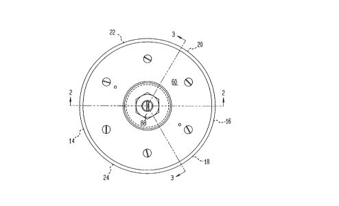
Flgure 1 ls a plan or top vlew of the novel
regulator, accordlng to an embodlment thereof;
Flgure 2 ls a cross-sectlonal view of the regulator
of Figure 1, taken along section 2-2 of Figure 1, the scale of
Flgure 2 belng slightly enlarged over the scale of Flgure l;
Flgure 3 is a cross-sectional vlew of the regulator
of Figures 1 and 2, taken along sectlon 3-3 of Flgure 1, the
same being of substantlally the same scale as Flgure 2;
- 2a -
- 72432-80
,~,...
Q 9 6
Figure 4 is an illustration of a portion of ehe regulator, showing the
valve seat and valving elemen~, the same representing the pressures and forces
acting acros~ the element; this figure too is slightly enlarged over the scale
of Figures 2 and 3; and
Fi~ure 5 is an illustration similar to thae of Figure 3, albeit of an
alternative ~Q~;~Pnt of the invention.
Descrlption of the Preferred ~o~i~e..t
The novel regulator 10, according to an embodiment thereof, has a regulator body12 in which are formed six connection ports ~only four of which are shcwn). Ports
14 and 16 ~Cc~ n~te ~or the inlet and discharge, respectively, of a heating
~1uid. Ports 18 and 20 ~cc~mro~te for the admittance of high-pressure natural
gas, and discharge of low-pressure gas, respectively. Two further ports 22 and
24, indicated by the dashed lines in Figure 1, not seen, are pro~ided for an inlet
gauge and an outlet gauge or relief valve, respectively, according to a practicewell known in this art.
The regulator body 12 has a central void 26 which is threaded partly therealong.The void threadedly receives therein a ccntrol valve body 28. Body 28 has a
cylindrical bore 30 formed therein with an annular recess 32 fonned in an outer
termination of the bore 30. An apertured valve seat 34 is see in the recess 32.Contr~l valve body 28 further has an outer, annular, reduced diameter portion 36about which is posltioned a cylindrical filter 38. Bore 30 opens onto a channel
40 formed in the bcdy 12, and at the opposite end thereof, terminates in a cylin-
drical recess 42. A valving element 44, having a tapered-nose head 46 and an
elongate shank 48, is confined within bore 30; the shank 48 is received at an end
thereof in the recess 42, and the leading er~ of the head 46 is received in the
valve seat 34.
An ~p~.,.~ portion of the regulator bcdy 12 has a circular recess 50 formed
therein which, centrally thereof, is in ,luid communication with the channel 40.Integral with the head 46 is a slender scem j2. The stem 52 protrudes through
the channel 40 and the recess 50. The shank 48, head 46 and stem 52 have a con-
tinuous p~ss~ge 54 formed therein and there~hrough. The passage 54 opens at cre
end thereof onto the recess 50, and at the other end onto the shank-receiving
recess 42. Abcut the lower portion of the shank 48 is disposed an 0-ring seal
~ ~-14~ 9 6
5~. A rimmed plate 56, centrally apertured, is set atop the 0-ring seal 55.
Plate 56 ccmprises a bearing surface for an end of a compression spring 58 whichis circumjacent the shank 48; the opposite end of the spring 58 is set against
an underlying, annular shoulder of head 46.
A hollcw bcnnet 60, having a radially-extending flange 62 is bolted, via the
flange 62, to the ~per~nst portion of the regulator body 12. A diaphragm 64
is clamped, by means of ies outer periphery, between the flange 62 and the bcdy 12.
The dia~.~a~l, 64 is centrally apereured, and receives therethrough an insert 66.
Insert 66 has a circular, plate-like portion 68 ~hich underlies the diaphragm,
and a threaded stub 70 which extends above the diaphragm 64. A diaphragm plate
72 is set about the stub 70 and a lock nut 74 is made fast on the stub and against
the plate 72. The insert 66 has a threaded bore 76 formed therein, and receivestherein the threaded end 78 of stem 52. A compression spring 80 is set, at one
end thereof, about the nut 74 and upon plate 72. The opposite end of the spring80 receives therein a button 82. An ad~ustment screw 84, which protrudes throughthe ~ LII~st end of the bonnet 60, and is threadedly engaged with a threaded
bore 86 thereat, bears against the button 82, and externally of the bonnet 60
receives a jam nut 88. Portion 68 of the insert 66 has a groove 90 formed thereln
which exte~ds fully thereacross.
A centrally-bored bowl 92 is made fast to an underside of the rP~ tor body 12.
The body 12 has a threaded bore 94 fonned in the underlying p~rtion ~-efeof to
receive therein the headed bolt 96 which secures the bowl 92 in place. Channels
98 and 100 formed in the body are in open communication with the parts 14 and
16. Consequently,then, a heating fluid, such as vehicular coolant, being admitted
via pcrt 14 will course through channel 98, to pool in the bowl 92, and e~it viachannel 100 ant po.C 16. The depeh of ~he bowL is such that heating f'.uid ccn-
ducted thereto can heat ~hd,~e, direcely, wieh che control valve body 28, and
tnat portion of the regulator body 12 in which are confined the filter 38 and
valving element 44 has the fluid addressed co opposite sides thereof and there-
abouc. Conse~uently, icing of the regulator 10 is prevented.
The di~ph~.. 64 forms one wall which closes off the recess 50, and this forms
an outer chamber of the recess, and that amGunt of void 26 in the regulator body12 which is not occupied defines an inner chamber thereof. The high pressure
natural gas enters the inner chamber, i.e., void 26, via the port 1~, and passesthr~ugh the ~ilter 38. Herein, the gas is mecered by the balanced valving
element 44. With particular reference to Figure 4, the balancing of the element
44 can be readily understood. The seating area between the head 46 of the valving
element 44 and the valve seat 34 defines a first boundary between the inlet gas
pressure, in the inner chamber of void 26, and the outlet gas pressure in the
outer chamber of recess 50. The gas pressure differential thereat creates an
upwardly directed force, the magnit~de of which varies p.opo-~ionally with the
differential pressure. The passage S4 in ~he valving element 44 communicates
the outlet gas pressure in the ou~er chamber of recess 50 co a volume obtaining
beneath the valving element 44 in the recess 42. Consequently, a second boundarybe~een the inlet pressure, in the inner chamber of void 26, and the outlet
pressure in the recess 42, is defined between the shank 48 and the 0-ring seal
55. The gas pressure differential thereat creates a downwardly directed force,
the msgnitude of which varies proportionally with the differential pressure.
In Figure 4, the locus ~f the inlet pressure is represented by "Pi", and that
of the outlet pressure is represented by "Po". The two, aforesaid boundary areas,
one where the head 46 engages the seat 34, and the other, the sealing area
bet~Fl the shank 48 and the 0-ring seal 55, are of the same diameter "Y'. As
a c ~ceq~nce, the oppositely directed forces "~' are e~ ~lized in magnitude.
Too, regardless of hcw the inlet pressure "Pi" and/or the cutlet pressure "Po"
varies, the forces and magnitude of the differential pressures, at the two
boundary areas, will be maintained in balanced opposition.
The spring 58 provldes an upward force to move the valving element 44 upwardly,
when nc other forces are present. Additionally, the spring 58 applies a biasing
force on the rimmed plate 56. The plate 56 maintains the geometry of the 0-ring
seal 55 so ehae the latter can positively seal against the shank 48.
-- 5 --
As earlier noted, portion 68 of the diaphragm insert 66 has the ~roove 90 formedtherein and fully thereacross. This feature permits gas flow, via the groove 90,even when the diaphragm has bottomed against the ~ppeL~I~st surface of the regu-lator body 12. This is especially beneficial in a using vehicle which has a
compressed natural gas system with a supply shut off. The groove 90 insures
an instant outlet pressure availability when the system supply is turned on.
To operate the regulator 10 and set the outlet pressure, the end user turns the
adjustment screw 84 to move the button 82 downwardly. This compresses the spring80 which forces the diaphragm 64 downwardly. Such movement of the diaphragm 64
co~c~mitantly moves the valving element 44 downwardly. Resultantly, the head 46
removes from the valve seat 34 to open communication between the inner chamber
of void 26 and the cuter chamber of recess 50. As the inlet pressure is much
greater than ~heoutlet pressure, gas flow will occur, and the outlet pressure
will increase. The outlet pressure acts against the surface of the diaphragm 64
exerting an upward force opposing the bias of the spring ~0, to effect an equil-ibrium. If the spring force increases, the outlet pressure will increase to
maintain the e~ rium. Too, if ~he inlet pressure diminishes, as wnen the
pressure in the supply cylinder decreases, the aforesai~ e~lilibrium will remain~ ~ILd,~ed; this is due to the aforedescribed balanced valving feature. This is
a novel advantage ~hich allows just a single regulator 10 of this design to
meet the needs of a compressed natural gas vehicle.
me alternative Pmhc~mPnt lOa of the invention, shown in Figure 5, pr~vides a
communication for the gas flow directly to an outlet port, rather than having the
gas work against the di~ a~", for advantages noted in the following. In Figure
same or s;mtl~r index nLmbers denote same or similar parts and/or c~.~ e.~ts as
those so-indexed in Figures 2 and 3.
In circumstances where there are high flow rates of the subject gas, there obtairs
the possibility of di~ ~a~l~ 64 and diaphragm insert 66 os~ rion or instabili~.
Co~ee~ tly, then, the Ir~.~"L~m or force of the gas would en~eavor to move ehe
valving el~Ton~ 44 to a closed position. Fm~c~;mpnt lOa of Figure 5 elLmQnates ~~~
aforenoted instability and closure of the valving element 44, by providing a pass-
age 102 which directly commLnicates the void 26, i.e., the inner chamber, wi~h
the gas discharge port 20. Whereas port 20, in embodiment 10 had a large pass-
age 20' opening onto the outer chamber, i.e., between the diaphragm 64 and the
recess 50, it is replaced, in this embodiment 10a, with a droop correction or
aspirator hole 104. The latter is provided to reduce the pressure drop which
is associated with increasing flow rates. Too, with the provisioning of the
passage 102, in bypass of the diaphragm 64, the groove 90 in the diaphragm
insert 66 is not necessary in embodiment 10a; it can be omitted.
The anticipated primary application of the reguiators 10 and 10a, as noted herein,
is as pressure reducers for high pressure, compressed natural gas-fueled vehicles.
Other applications, however, can be found in controlled pressure reductions of
compressed gases in industrial and research endeavors where additional heat input,
to prevent moisture freezing or excessive cooling, is required.
While I have described my invention in connection with specific ~mbc~;ments thereo~,
it is to be clearly understood that this is dcne only by way of example, and notas a limitation to the scope of the invention as set forth in the objects thereof
and in the appended claims. For example, in lieu of the adjustment screw 84, a
screw, such as a set screw or the like, could be used and factory-set and sealed,
with a plug, epoxy, or such, to render the regulator 10 or 10a t~l~eL~Loof. In -
addition, vehicular coolant need not be the cnly medium for heating the regulatcr
10 or 10a to prevent or inhibit icing thereof. Electrical heating could be usedas well and, for employing the bowl 92, it would be most facile to connect an
electrical heating el~,~nt thereto and arrange electrical connectors therefor
wherever most convenient and accessible. Such further alternative features willsuggest themselves eo others by taking teaching from my disclosure herein, and --e
deemed to be within the ambit of my invention and embraced by the appended clai-s