Note : Les descriptions sont présentées dans la langue officielle dans laquelle elles ont été soumises.
CA 02120948 2004-02-17
~ 63970-50
1
AN INSPECTION DEVICE FOR DETECTING SURFACE FAULTS, AND AN
INSTRUMENT INCORPORATING SUCH A DEVICE
Technical Field
The invention relates to a device and to an
instrument for the non-destructive testing of tubular
members, by discovering, localizing and reproducing surface
flaws and faults such as cracks that may be present in the
inner surfaces of the tubular members. The invention finds
particular application in the inspection of tubular members
of small inner diameters.
Technical Standpoint
Heat exchanges such as steam generators in nuclear
power stations are equipped with high-load heat exchanger
tubes having an internal diameter of 15-20 mm. The tubes
are secured by rolling the tubes in end walls which form
tube attachments and partition walls that mutually separate
the heat-carrying media passing through the heat exchangers.
The vulnerability of the tubes to load caused by pressure
and heat and by changes in these factors, vibrations,
corrosion, etc., can result in flaws and faults, such as the
formation of cracks in the tube walls. If these flaws are
not rectified in time, the flaws may become so serious as to
cause the tubes to rupture, resulting in serious
consequences. It is therefore important to constantly
monitor the tubes, so that necessary measures can be taken
in time. In the case of steam generators, damaged tubes can
be plugged at the time of making an annual inspection.
Different non-destructive testing techniques are
used to detect surface flaws, of which techniques inductive
testing has been one of the few techniques applied for
CA 02120948 2004-02-17
63970-50
la
testing deep into small bore pipes and tubes. In this
technique, there is inserted into the tubular member to be
tested a probe which is equipped with a coil to which
alternating current is supplied and which functions to
induce eddy currents in the wall of the tubular member which
retroact on the coil. Because the
CA 02120948 2003-09-16
63970-50
2
eddy currents are influenced by flaws in the tubular member,
some information can be obtained as to whether or not a flaw
exists and, if so, the size of the flaw, by measuring the
retroactive effect of the eddy currents on the coil. One
pronounced drawback with this known method of inspection,
however, resides in the difficulty experienced in
determining the nature of the flaw, and in that the signal
interference ratio is small. Not only small flaws are
hidden by interference noise. For instance, if the probe is
constructed to produce good indications of the presence of
longitudinally extending cracks, which are the most common,
equally as large transversely extending cracks will only
result in small readings (output signals) which are
difficult to distinguish in the interference noise.
Disclosure of the Invention
Technical Problem
The object of the present invention is to provide
a device and an instrument for detecting internal surface
flaws in tubular members. The device is intended to provide
a more accurate understanding of the flaws than has hitherto
been possible with known methods.
Solution
In one aspect of the invention, there is provided
a device for use in detecting surface faults or flaws in the
inner surface of a tubular member, characterized in that the
device comprises an elastic body and penetrant absorbent
surfaces; and in that the body is adapted to be moved to an
area of the inner surface chosen for inspection, expanded to
a state in which the absorbent surfaces abut the inner
surface of said tubular member, and contracted so as to
CA 02120948 2004-02-17
63970-50
2a
distance the absorbent surfaces from the inner surface of
said tubular member.
In a second aspect, there is provided an
instrument for use when detecting surface faults or flaws in
tubular members, comprising the device recited in the
immediately preceding paragraph, characterized in that the
instrument also comprises means for delivering penetrant to
that area of the inner surface of the tubular member chosen
for inspection; in that said means is combined with the
device to form an inspection probe; in that said means
includes two units which are mutually spaced in the
longitudinal direction of the tubular member and which are
intended to seal between parts of said means and the
surrounding tubular member such as to form in said tubular
member a substantially closed, limited space which can be
filled with penetrant, and in that the inspection probe is
movable in the tubular member between a first position in
which that area of the inner surface of said tubular member
selected for inspection is included in the part surface
which is located between the sealing units, and a second
position in which the device is surrounded by said area of
the inner surface selected for inspection.
In the case of one known method for the non-
destructive testing of surfaces, flaws which are otherwise
invisible are treated so that they can be seen with the
naked eye. A so-called penetrant, i.e. a liquid which is
able to penetrate into very fine cracks, is applied to the
test surface with the aid of a brush for instance. The
penetrant also has the ability to remain in the surface
fault when the test surface is subsequently washed to remove
excessive penetrant that has not penetrated into the surface
faults. When a coloured penetrant is used, the test surface
CA 02120948 2003-09-16
63970-50
2b
is sprayed with a so-called developer which contains a fine-
grain white powder. The penetrant is drawn out of the
cracks by
WO 93/07475 . PCT/SE92/00716
3
2120948
the powder layer and disperses in the layer so as to form contrasting
indications on cracks having a width down to 0.001 mm. On the other
hand, when a fluorescent penetrant is used, it is possible to observe
indications directly with the aid of ultraviolet light. This method,
however, presumes that the test surface can be easily reached.
Consequently, it has not been possible to apply this method on the
internal surfaces of long, narrow tubular members.
The present invention also includes the treatment of a test surface
with a penetrant and the removal of excessive liquid. However, instead
of viewing the indications directly on the test surface, the penetrant
take-up by the fault or flaw is transferred to the surface of a devi-
ce such as to leave an imprint of the indication and the device is
then removed from the inaccessible site of the flaw. This imprint can
then be studied in some appropriate manner. In order to obtain an
effective image transfer and to prevent the transferred indications
from being impaired as the device is removed from the tubular member,
it is proposed that the inspection device is expandable. Thus, the
device is inserted into the tubular member and brought to the inspec-
tion site while reduced in diameter to a size which will permit the
device to move through the tubular member in a generally frictionless
fashion, whereafter the device is expanded so as to bring the outer
surfaces of the device into effective contact with the test surface.
When penetrant has been transferred, the device is then constricted to
an extent which will enable it to be moved in the tubular member
essentially in a frictionless fashion and without risk of the indica-
tions being scraped from the surfaces of the device as it is moved out
of the tubular member.
The inspection device shall thus have two functions. Firstly, the
device shall include a body which can increase in thickness so as to
conform to the interior shape of the tubular member and also to
decrease in thickness, ard, secondly, the device shall include
surfaces which can be brought into contact with the inner surfaces of
the tubular member and absorb penetrant, and possibly also disperse
said penetrant so as to provide readily observed indications, and to
retain these indications for the length of time required to carry out
said observations. These two operational modes can be achieved with
PCT/SE92/00716 .
WO 93/07475
4
one and the same element, or alternatively the device may, for
instance, be comprised of an expandable body and stretchable sheeting
which surrounds said body and onto which penetrant can be transferred. .
The body can be made expandable in several different ways. For
instance, the body may have an elastic construction and include a
cavity or hollow into which pressure medium is introduced, or the end
walls of a normally cylindrical body may be pressed towards one
another. A suitable surface is obtained when the body or the surroun-
ding sheeting is made of a polymeric material, such as polyurethane.
An outer surface which possesses the aforesaid desired properties can
be obtained when the contact surface of the body or the penetrant
absorbing sheeting has a structure which exhibits a large number of
shallow pits, such as the surface structure obtained by fine-grinding
processes.
In order to enable the invention to be applied industrially, there is
proposed an instrument which, in addition to the~inspection device,
includes a device for applying penetrant to and removing excessive
penetrant from an internal tubular surface, and a device for handling
the inspection device and the penetrant applying device and for
introducing said devices into the tubular member and removing the same
therefrom. The instrument may also include a member which functions to
dry-up any rinsing liquid that remains in the tubular member. The
inspection device and the penetrant applying and rinsing device are
mounted in line with one another with the surface drying member
located therebetween, so as to form a unit whose one end is attached
to one end of the handling device.
The penetrant applying and rinsing device includes two mutually
spaced, closed walls whose peripheral surfaces are intended to seal
against a surrounding tubular surface. These walls thus delimit a
space in the interior of the tubular member, the wall surface located
between the seals being the subject of a penetrant application and
rinsing operation. The space is first filled completely with penetrant
through one of the media conveying lines connected to the handling
device. The liquid penetrant is then allowed to act over a period of
WO 93/07475 PCT/SE92/00716
2.~2(~948
time, whereafter the space is emptied and the space then flushed with
clean water so as to rinse the wall surfaces clean.
The space is then emptied of rinsing water and the unit as a whole is
then displaced with the aid of the handling device to a position in
which the drying member is located within the region of the tubular
surface to which penetrant has been applied and which has been subse-
quently rinsed. The drying member includes a part which, similar to
the expandable inspection device, can be caused to expand or swell and
made to conform to the shape of the tubular inner surface and pressed
thereagainst. Since that part of said component which is pressed
against the tubular surface is comprised of a liquid-absorbent materi-
al, the component will remove any residual droplets of surface rinsing
water.
The drying member is then constricted to a smaller diameter and the
whop of the unit is moved further along the tubular member to a
position in which the inventive inspection device is located within
the penetrated, rinsed and dried region of the tubular wall.~Any
penetrant that has penetrated a flaw, e.g, crack, is then transferred
to the surface of the inspection device in the aforedescribed manner.
The unit is then withdrawn from the tubular member, with the aid of
the handling device, for study of those indications that may be
imprinted on the surface of said device.
The handling device may, for instance, have the form of a tube or,
when testing curved tubular members, may have the form of a flexible
but rotationally rigid hose through which the conductors required to
operate the unit are drawn. Because movement of the unit in the
tubular member is solely translatory, an indication of the location of
an indicated surface flaw or fault in the tubular member can be
obtained by recording the distance through which the unit is inserted.
These imprints can be recorded with the aid of known optical techni-
ques and documented as a stage in routine safety checks.
The invention can be used in tubular members of different sizes and
intended far different purposes, for instance in the tubes of steam
boilers and different process equipment. The invention is not limited
WO 93/07475 ~ ~ ~ ~ ~ ~ ~ PCT/SE92/00716
6
to the non-destructive testing of standard tubular members. It can
also be used effectively for inspecting, for instance, square tubular
members of non-uniform crossdimensions. Neither is the invention
restricted to the use of optically readable indications. For instance,
the penetrant may contain a radioactive substance and therewith enable
other reading methods to be applied.
Advantages
Application of the invention provides an effective supplement to other
inspection methods, so as to enable a more universal inspection to be
carried out. The same feed mechanism that is used to insert other
instruments into the tubes of steam generators can also be used to
feed the inventive unit into and out of a tubular member. The ability
to operate at distances through lines enables different operating
means, such as pumps, etc., to be located at the most suitable places.
Brief Oescri~tion of the Drawin4s
The present invention will now be described in more detail with
reference to a preferred exemplifying embodiment thereof and also with
reference to the accompanying drawings, in which like parts have been
identified like reference numerals.
Figure 1 is a longitudinal section view illustrating the preferred
embodiment of the instrument and the inspection device.
Figures 2a, 2b and 2c illustrate the modus operandi of the instrument
in three stages, with the active components being shown in each step.
For the sake of illustration, the instrument is shown compressed
longitudinally and some of the elements have been overdimensioned.
Qescription of a Preferred Embodiment
A preferred embodiment of an inventive instrument includes a probe
which is normally used in an upstanding position, and a handling
device which is used to manoeuver the probe and which in the
illustrated embodiment comprises a number of hoses housed in a
WO 93/07475 PCT/SE92/00716
flexible tubular casing attached to the probe. The hoses function to
conduct various media and are connected at one end to pipes provided
in the probe, as described below, while the other ends of respective
hoses are connected to a service unit which includes pumps, control
equipment, etc. As will be seen in Figure 1, the probe comprises three
main parts. A first main part 1 is intended for applying penetrant to
a test surface and for rinsing away excessive penetrant . A second
main part 2 is intended for drying the test surface, while the third
main part 3 is intended to image possible surface flaws in the test
surface. All of the main probe parts include expandable functional
elements. These elements may be of the kind which can be expanded by
exerting pressure from the sides thereof. In the case of the illustra-
ted embodiment, however, the expandable elements include cavities or
hollows and are expanded by placing the cavities under pressure with
the aid of a medium introduced through the aforesaid hoses.
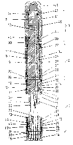
The probe body has in the form of a tool-machined shaft 4 whose
cylindrical outer surface includes three in-line cylindrical surfaces
5, 6 and 7. As will be seen from Figure 1, the diameters of the
cylindrical surfaces decrease in an upward direction and each of said
surfaces provides a position for the respective functional elements of
the three main parts of the probe. Three pressure-media conducting
channels 8, 9 and 10 are drilled in the shaft 4. The first channel
openings are located in the lower end-surface 11 of the shaft, while
each of the second channel openings are located in a respective
cylindrical surface 5, 6 and 7.
The main probe part 1 intended for applying penetrant and rinsing away
excessive penetrant includes two coaxial and mutually spaced plungers
12, 13, each of which is provided with respective functional elements
14, 15 which serve as gas-tight seals in delimiting a space in which
the tubular member shall be inspected or tested. The first plunger 12
is formed by the lower part of the shaft 4 and includes the cylindri-
cal surface 5, which is the surface that has the largest diameter.
This cylinder surface forms a position for solely one of the two sea-
ling units of said main probe part and is much shorter than the other
two cylinder surfaces 6, 7 on the shaft. The bottom of the plunger 12
WO 93/07475 PCT/SE92/00716
21~0~48
8
is terminated with a flange or lip 16 whose outer diameter is slightly
smaller than the inner diameter of the tubular member to be inspected.
The second plunger 13 located below the first mentioned plunger 12 is
comprised.of the upper end of a further element, called structural
element 17, whose upper part has a configuration identical to the
configuration of the first plunger 12 but in mirror image. The lower
end 18 of the structural element 17 is cylindrical and has a diameter
which is adapted to form an attachment for the earlier mentioned
flexible tubular casing of the flexible handling device 19 by means of
which the probe is manoeuvered in the tubular member. The structural
element 17 is provided with five penetrating throughlets which
sealingly accommodate five pipes, of which three, 20, 21 and 22,
extend up past the interspace between the structural element 17 and,
the end surface 11 of the. shaft 4 and are sealingly connected at this
end surface to the aforesaid channels 8, 9 and 10. As before
. mentioned, these pipes are connected to the hoses in the casing 19 and
also form a bridge by means of which the plungers are connected to one
another. Of the two remaining pipes, one pipe functions as an inlet
and outlet pipe 23 and is open at the upper end surface of the
structural element 17, whereas the other pipe functions as an overflow
24 and extends through practically the entire interspace and is
terminated immediately beneath the end surface 11 of the shaft 4.
Each of the mutually identical sealing units 14, 15 includes a hose
piece 25, 26 made of a flexible material, such as a silicone polymer,
having straight cut ends, a pair of terminal rings 27 which are
reduced in diameter to form collars on which the ends of the hose
pieces are fitted, and a pair of clamping rings 28 for securing the
hose ends on the collars of the terminal rings. The terminal rings
have cylindrical inner surfaces whose diameters slightly exceed the
diameter of the lowermost cylinder surface 5 on the shaft 4 and which
are fitted with internal 0-ring grooves and corresponding 0-rings. The
sealing units 14, 15 have the same length as the aforesaid cylinder
surface 5 and thus also a corresponding. surface 29 on the structural
element 17 and are mounted on said surfaces and locked by first lock
nuts 30, 31 through the agency of screw threads 32, 33 provided
WO 93/07475 . PCT/SE92/00716
212Q~4g 9
externally of respective cylinder surfaces on the shaft and the
structural element.
The second main probe part 2 intended for drying the rinsed surfaces
of the tubular member comprises a functional element in the form of a
drying unit 34 which is mounted on the intermediate cylinder surface 6
of the shaft 4 and the length of which corresponds to the length of
said intermediate cylinder surface 6 and slightly exceeds the distance
between the structural element 17 and the shaft 4. The drying unit 34,
is constructed in a manner similar to the aforedescribed sealing
units, but with the exception that it is much longer than said units.
The drying unit also includes an elastic hose 35, made of a silicone
polymer for instance, on the outside of which there is fitted a sleeve
36. The sleeve 36 consists of a water-absorbent sheeting, fc>r instance
a porous nonwoven cloth, whose length is equal to the length of the
hose 35 and the ends of which sheeting and hose are clamped between a
pair of clamping rings 37 and terminal rings 38 of the same kind used
with the sealing units. The inner diameter of the terminal rings is
slightly larger than the diameter of the intermediate cylinder surface
and the rings are provided with 0-rings which seal against said cylin-
der surface. The whole of the drying unit is mounted on the cylinder
surface in abutment with the first lock nut 30 which secures the sea-
ling unit 14 on the shaft 4. The drying unit is locked against axial
movement on the shaft 4 by the second lock nut 39 screwed on said
shaft.
The third main probe part 3 that functions as an expandable body for
imaging surface flaws has a functional element in the form of a in-
spection unit 40 mounted on the uppermost cylinder surface 7 of the
shaft. As will be seen from Figure 1, the unit 40 has the same length
as the cylinder surface 7. The inspection unit comprises an inspection
tube 41 which is stepped down at respective ends thereof so as to
receive two end sleeves 42, 43. The inspection tube is made of an
elastic material, such as polyurethane having a finely ground outer
cylindrical surface. The distance between the two stepped ends of the
tube 41 is somewhat shorter than the distance between the plungers 12,
13 and the outer diameter of said tube is adapted to the diameter of
the tubular member to be inspected. Similar to the end sleeves 42, 43,
WO 93/0747.5 PCT/SE92l00716 r
2~~U~48 Io
the tube 40 has an inner diameter which corresponds to the diameter of
the cylinder surface 7. Two 0-rings 44, 45 are mounted in the outer
surface of the shaft 4 and function to seal against the tube 4I in-
wardly of the end sleeves. The inspection unit 40 is locked against
axial movement on the shaft 4 in abutment with the second lack nut 39
by an end nut 46 which is screwed on a corresponding screw thread at
the top of the shaft.
Method of Operation
A robot positions a feed mechanism (not shown) in the lower part of a
steam generator, beneath the tubular member 47 chosen for examination.
The feed mechanism then pushes the instrument probe up into the tube,
with the aid of the probe handling device 19, until the two plungers
I2, 13 of the penetrant applying and penetrant rinsing main probe part
1 lie above and beneath a desired inspection area 48, of the tubular
member (see Figure 2a). Air pressurized to about 2 bars is injected
from the service unit into the spaces located inside of the hose
pieces 25, 26 of the sealing units, via the pipe 20, a radial hole 49
in the plunger 13 to the pipe 20, and the passage 8, so as to press
the sealing units 14, 15 outwardly and therewith provide a seal
between the plungers 12, 13 and the surrounding tubular member.
Subsequent to having delimited an inspection space 50 in the tubular
member, including the inspection area 48, the space is filled with a
penetrant which is pumped from the service unit through the inlet and
outlet pipe 23, until penetrant passing through the overflow pipe 24
and associated hose in said casing runs out through the hose outlet in
the service unit, whereupon the supply of penetrant is discontinued.
The inspection space 50 has then been filled essentially completely,
due to the flow resistance in the overflow pipe and associated hose.
The penetrant is then allowed to act for a given period of time,
whereafter the space is emptied through the inlet and outlet pipe 23
with the aid of said pump, with a reversed pumping action.
Cleaning water is then delivered to the inspection space 50 in the
same manner as the penetrant. This water flows through the space to
the overflow pipe 24 and rinses the inspected surface over a period of
time, whereafter the space is emptied by reversing the pump.
WO 93/07475 PCT/SE92/00?16
11
Pressure on the sealing units 14, 15 is then relieved so that the
sealing units will return to their original state, whereafter the
entire probe is moved down in the tubular member 47 with the aid of
the probe handling device 19 and the feed mechanism, until the main
probe part 2 intended for drying the inspected area is located within
the inspection area 48 (Figure 2b). Air under a pressure of about 2
bars is then introduced from the service unit, through the pipe 21 and
the passage 9, so as to press the elastic hose 35 of the drying unit
34 uniformly against the tubular member 47, with the waterabsorbent
sleeve 36 between the hose and said tubular member. The sleeve will
therewith soak up any water droplets that remain. Subsequent to
interrupting pressurization of the elastic hose 35 and after the
elastic hose has returned to its original state, the sleeve 36 is
permitted to expand so as to further increase its absorbency. The
rinsed surface can be dried in several stages, by withdrawing the
probe in small consecutive steps.
When penetrant has been delivered to the inspection area of the
tubular member and excessive penetrant has been removed, the probe is
then drawn down through a distance which will bring the imaging main
part of the probe within this treated area (see Figure 2c). Pressuri-
zed hydrauhic fluid is then delivered from the service unit through
the pipe 22 and the passage 10 to the interior of the tube 41 so as to
expand the tube and press it against the inner wall of the tubular
member, so as to transfer any penetrant that has penetrated a flaw to
the surface of the inspection tube. The hydraulic fluid is delivered
at a pressure of about 70 bars, which corresponds to the differential
pressure to which the steam generator tubes are subjected in opera-
tion. The hydraulic fluid is then evacuated from the inspection tube,
so that the tube will return to its original state and the probe can
be withdrawn from the tubular member 47. The whole of the process
described, including robotics guiding of the instrument, the operation
of the instrument feeding mechanism, the operation of the service
unit, etc., can be controlled by a computer. Subsequent to having
removed the probe from the tubular member, the drying member 34 and
the inspection unit 40 can be removed from the shaft, by removing the
two uppermost nuts 39, 46, therewith enabling two fresh units to be
mounted on the shaft in preparation for another inspection.