Sélection de la langue

Search

Sommaire du brevet 2122176 

Énoncé de désistement de responsabilité concernant l'information provenant de tiers

Une partie des informations de ce site Web a été fournie par des sources externes. Le gouvernement du Canada n'assume aucune responsabilité concernant la précision, l'actualité ou la fiabilité des informations fournies par les sources externes. Les utilisateurs qui désirent employer cette information devraient consulter directement la source des informations. Le contenu fourni par les sources externes n'est pas assujetti aux exigences sur les langues officielles, la protection des renseignements personnels et l'accessibilité.

Disponibilité de l'Abrégé et des Revendications

L'apparition de différences dans le texte et l'image des Revendications et de l'Abrégé dépend du moment auquel le document est publié. Les textes des Revendications et de l'Abrégé sont affichés :

  • lorsque la demande peut être examinée par le public;
  • lorsque le brevet est émis (délivrance).
(12) Brevet: (11) CA 2122176
(54) Titre français: ELEMENT DE COMMUTATEUR BIMETALLIQUE
(54) Titre anglais: BI-METALLIC SWITCH ELEMENT
Statut: Périmé et au-delà du délai pour l’annulation
Données bibliographiques
(51) Classification internationale des brevets (CIB):
  • H01H 37/52 (2006.01)
  • H01H 1/58 (2006.01)
  • H05B 41/06 (2006.01)
(72) Inventeurs :
  • KULIK, JOSEPH S. (Etats-Unis d'Amérique)
  • VINCENT, ROBERT J. (Etats-Unis d'Amérique)
  • BAZIN, SIMONE P. (Etats-Unis d'Amérique)
(73) Titulaires :
  • GTE PRODUCTS CORPORATION
(71) Demandeurs :
  • GTE PRODUCTS CORPORATION (Etats-Unis d'Amérique)
(74) Agent: R. WILLIAM WRAY & ASSOCIATES
(74) Co-agent:
(45) Délivré: 2000-10-17
(22) Date de dépôt: 1994-04-26
(41) Mise à la disponibilité du public: 1994-10-31
Requête d'examen: 1997-09-11
Licence disponible: S.O.
Cédé au domaine public: S.O.
(25) Langue des documents déposés: Anglais

Traité de coopération en matière de brevets (PCT): Non

(30) Données de priorité de la demande:
Numéro de la demande Pays / territoire Date
8/056,006 (Etats-Unis d'Amérique) 1993-04-30

Abrégés

Abrégé anglais


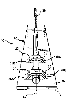
A bi-metallic switch element 10 has a contact wire 26 attached thereto by
means of
a plurality of crimps. A first crimp 28 applied at a first pressure fixes the
contact
wire to the element and a second crimp 30, formed at a lesser, more controlled
pressure aligns the contact wire in a predetermined location.

Revendications

Note : Les revendications sont présentées dans la langue officielle dans laquelle elles ont été soumises.


The embodiments of the invention in which an exclusive
property or privilege is claimed are defined as follows:
1. A bi-metallic switch element comprising: an
elongated bi-metallic member having a longitudinal axis
and comprised of a relatively high expansion material and
a relatively low expansion material in operative, intimate
contact with one another; and two spaced apart tunnels
formed in a first end of said member and projecting
upwardly from said high expansion material, said tunnels
being spaced apart from one another and aligned along said
longitudinal axis.
2. The bi-metallic switch element of Claim 1
wherein an elongated, electrically conductive contact wire
has one end thereof positioned in said tunnels.
3. The bi-metallic switch element of Claim 2
wherein another end of said contact wire projects beyond a
second end of said elongated bi-metallic element.
4. The bi-metallic switch element of Claim 3
wherein each of said tunnels is crimped to said wire, each
of said tunnels thereby separated into two tabs, said tabs
being asymmetric with respect to said longitudinal axis,
and the tabs of the first of said tunnels being asymmetric
with respect to the tabs of the second of said tunnels.
5. A bi-metallic switch element comprising: an
elongated bi-metallic member having a longitudinal axis
and comprised of a relatively high expansion material and
a relatively low expansion material in operative, intimate
contact with one another; two spaced apart tunnels formed
in a first end of said member and projecting upwardly from
said high expansion material, said tunnels being spaced
apart from one another and aligned along said longitudinal
axis; an elongated, electrically conductive contact wire
having one end thereof positioned in said tunnels; and

crimps formed in said tunnels, a first crimp formed in a
first of said tunnels fixing said wire to said bi-metallic
element and a second crimp formed in a second of said
tunnels positioning said wire in a predetermined location
relative to said bi-metallic element.

Description

Note : Les descriptions sont présentées dans la langue officielle dans laquelle elles ont été soumises.

... ". .v . s ...,. .. _ , . .. ~'Q.,:.n..; itko.',.. ~..m. . ,..r_. , >..,..
.~.. ".
r ~~z~~~~~~3u~5
~3-~-428
~I-METALLIC ~V~ITC~d ELEMENT
TEIrI-INICAL FIELD
This invention relates generally to bi-metallic switch elements and more
particularly
to such elements having better control over the location of a contact wire
which is a
part of the element. The element can form a part of a switch which can be
employed in the starting circuitry of high intensity discharge lamps.
EACKG~3gINI) ART
The basic elements of a bi-metal switch include at least a bi-metal member
which
usually is elongated and which can have a contact wire attached thereto.
Generally,
it is important that the contact wire be accurately positioned on the bi-
metal. Two
major forms of attachment have been employed in the past. A first simply
involves
welding the contact wire to the bi-metal and a second involves attaching the
wire by
means of a crimp. 'The latter method has been accomplished by stamping either
a
tunnel or a pair of tabs from the bi-metal, laying a wire in the opening thus
provided, and crimping the tabs or tunnel to the wire. ~Nhile these methods
provided an adequate holding means for the wire they did not provide for
accurate
location, since very often the force applied to fix the wire disturbed
whatever
previous location had been determined.
DISCLi0SURIE ~F 1'FIE INVENTI~N
It is, therefore, an object of the invention to obviate the disadvantages of
the prior
art.
It is another object of the invention to enhance bi-metal switch elements.
Yet another object of the invention is the enhancement of the operation of bi-
metal
switch elements.
These objects are accomplished, in one aspect of the invention, by the
provision of a
bi-metallic switch element which comprises an elongated bi-metallic member
having
a longitudinal axis and comprised of a relatively high expansion material and
a
- Page 1- 93428b/word/0(~8
SfA
,T,v
iis,

93-1-428
relatively low expansion material in operative, intimate contact with one
another.
'Two spaced apart tunnels are formed in a first end of the member and project
upwardly from the high expansion material. The tunnels are formed transverse
to
the longitudinal axis. An elongated, electrically conductive contact wire has
one
end thereof positioned in the tunnels. Crimps are formed in the tunnels with a
first
crimp being formed in a first of the tunnels fixing the wire to the bi-
metallic element
and a second crimp being forned in a second of the tunnels for positioning the
wire
in a predetermined location relative to the bi-metallic element.
The employment of the plural tunnels allows for the use of differential
pressures for
each of the crimps and provides for control over the location of the contact
wire.
BRIEF 1)ES~RIPTI~1~ ~F TIE 1DRAWINGS
Fig. 1 is a perspective view of a bi-metallic element having a pair of contact
wire
receiving tunnels formed in one end thereof;
Fig. 2 is a perspective view of a bi-metallic element with a contact wire
crimped in
the tunnels; and
Fig. 3 is a side elevational view of a bi-metallic element illustrating a
placement of
the contact wire.
BEST l~~I)E FCDR CAR~t'YI1V~ ~UT ~E Il~N1'lf~N
Fox a better understanding of the present invention, together with other and
further
objects, advantages arid capabilities thereof, reference is made to the
following
disclosure and appended claims taken in conjunction with the above-described
drawings.
Referring now to the drawings with greater particularity, there is shown in
Figs. 2
and 3 a bi-metallic switch element 10 which comprises an elongated bi-metallic
member 12, shown by itself in Fig. 1, having a longitudinal axis 14 and
comprised of
a relatively high expansion material 16 and a relatively low expansion
material 18 in
operative, intimate contact with one another. A suitable material is ASTM B388
Type TMS. Two spaced apart tunnels 20 and 22, respectively, axe formed in a
first
- Page 2 - 93428b/word/0008

93-1-428
end 24 of member 12 and project upwardly from the high expansion material 16.
An
opposite end of the element 12 has a right angle bend formed therein to
provide a
wall 23. The tunnels are formed transversely to the longitudinal axis. An
elongated, electrically conductive contact wire 26, which preferably is formed
from a
high tensile tungsten wire such as NS-55I~1 which is avaliable from ~SRAM
SLYVANIA, Townada, Pennsylvania 18848, has one end thereof positioned in the
tunnels. (As used herein, high tensile designates wire having a strength of 67-
72
gm/mg/200m). A first crimp 28 is formed in a first of the tunnels, e.g., 20,
to fix the
wire 26 to the bi-metallic element 12. The crimp 28 causes an asymmetric
rupture
of the tunnel, as is shown in Fig.2, and provides what appears to be a pair of
tabs
28a and 28b. The asymmetry is caused by the use of an offset clamping punch. A
first, relatively high pressure is employed to form the crimp 28. A second
crimp 30
is formed in the second tunnel 22 and is used to position the wire in a
predetermined position relative to the bi-metallic element 12. 'The second
crimp 30
also provides an asymmetric rupture of the tunnel to form tabs 30a and 30b.
These
latter tabs ark asymmetric with respect to the tabs 28a and 28b and both sets
of tabs
are asymmetric with respect to the centerline 14.
The second crimp 30 is preferably formed at a lower pressure than the first
crimp to
aid in positioning the location of the wire. This can be accomplished by
making the
second set of clamping tools slightly longer than the first set. In the
embodiment of
the invention shown and described below, the second set of tools can be 0.003"
(0.0076mm) longer than the first set.
Ttte preferred location of the contact wire 26 is contiguous with the surface
of the
element 12 and aligned along centerline 14. As shown in Fig.3 by the dimension
"a", a small tolerance is acceptable. In a preferred form of the invention the
tolerance should be no greater than lmm for a switch element having a length
of
0.875" (2.223mm) and a width of 0.125" (0.318mrn). 'The tunnels have a width
of
about 0.040" (0.102mm) and can be separated by about 0.U46" -0.050" (0.117-
0.127mm). The transverse length of the tunnels is about 0.0625" (0.158mm).
While not limited thereto, the switch 10 described herein has greatly improved
the
operation of high intensity discharge lamps by providing an accurate cycle
time over
the life of the lamps.
- Page 3 - 93428b/word/0048

93-1-428
While there have been shown and described what are at present considered to be
the preferred embodiments of the invention, it will be apparent to those
skilled in
the axt that various changes and modifications can be made herein without
departing from the scope of the invention as defined by the appended claims.
_ page 4 - 93428b/word/0008

Dessin représentatif
Une figure unique qui représente un dessin illustrant l'invention.
États administratifs

2024-08-01 : Dans le cadre de la transition vers les Brevets de nouvelle génération (BNG), la base de données sur les brevets canadiens (BDBC) contient désormais un Historique d'événement plus détaillé, qui reproduit le Journal des événements de notre nouvelle solution interne.

Veuillez noter que les événements débutant par « Inactive : » se réfèrent à des événements qui ne sont plus utilisés dans notre nouvelle solution interne.

Pour une meilleure compréhension de l'état de la demande ou brevet qui figure sur cette page, la rubrique Mise en garde , et les descriptions de Brevet , Historique d'événement , Taxes périodiques et Historique des paiements devraient être consultées.

Historique d'événement

Description Date
Le délai pour l'annulation est expiré 2008-04-28
Lettre envoyée 2007-04-26
Inactive : CIB de MCD 2006-03-11
Accordé par délivrance 2000-10-17
Inactive : Page couverture publiée 2000-10-16
Préoctroi 2000-07-19
Inactive : Taxe finale reçue 2000-07-19
Un avis d'acceptation est envoyé 2000-01-21
Lettre envoyée 2000-01-21
Un avis d'acceptation est envoyé 2000-01-21
Inactive : Approuvée aux fins d'acceptation (AFA) 1999-12-29
Modification reçue - modification volontaire 1999-08-05
Inactive : Dem. de l'examinateur par.30(2) Règles 1999-05-05
Inactive : Lettre officielle 1998-06-05
Inactive : Supprimer l'abandon 1998-06-05
Réputée abandonnée - omission de répondre à un avis sur les taxes pour le maintien en état 1998-04-27
Lettre envoyée 1997-10-23
Inactive : Dem. traitée sur TS dès date d'ent. journal 1997-10-20
Inactive : Renseign. sur l'état - Complets dès date d'ent. journ. 1997-10-20
Exigences pour une requête d'examen - jugée conforme 1997-09-11
Toutes les exigences pour l'examen - jugée conforme 1997-09-11
Réputée abandonnée - omission de répondre à un avis sur les taxes pour le maintien en état 1997-04-28
Inactive : Demande ad hoc documentée 1997-04-28
Demande publiée (accessible au public) 1994-10-31

Historique d'abandonnement

Date d'abandonnement Raison Date de rétablissement
1998-04-27
1997-04-28

Taxes périodiques

Le dernier paiement a été reçu le 2000-04-05

Avis : Si le paiement en totalité n'a pas été reçu au plus tard à la date indiquée, une taxe supplémentaire peut être imposée, soit une des taxes suivantes :

  • taxe de rétablissement ;
  • taxe pour paiement en souffrance ; ou
  • taxe additionnelle pour le renversement d'une péremption réputée.

Veuillez vous référer à la page web des taxes sur les brevets de l'OPIC pour voir tous les montants actuels des taxes.

Historique des taxes

Type de taxes Anniversaire Échéance Date payée
Requête d'examen - générale 1997-09-11
TM (demande, 4e anniv.) - générale 04 1998-04-27 1998-04-27
TM (demande, 5e anniv.) - générale 05 1999-04-26 1999-04-15
TM (demande, 6e anniv.) - générale 06 2000-04-26 2000-04-05
Taxe finale - générale 2000-07-19
TM (brevet, 7e anniv.) - générale 2001-04-26 2001-04-02
TM (brevet, 8e anniv.) - générale 2002-04-26 2002-04-03
TM (brevet, 9e anniv.) - générale 2003-04-28 2003-04-02
TM (brevet, 10e anniv.) - générale 2004-04-26 2004-04-01
TM (brevet, 11e anniv.) - générale 2005-04-26 2005-04-01
TM (brevet, 12e anniv.) - générale 2006-04-26 2006-03-30
Titulaires au dossier

Les titulaires actuels et antérieures au dossier sont affichés en ordre alphabétique.

Titulaires actuels au dossier
GTE PRODUCTS CORPORATION
Titulaires antérieures au dossier
JOSEPH S. KULIK
ROBERT J. VINCENT
SIMONE P. BAZIN
Les propriétaires antérieurs qui ne figurent pas dans la liste des « Propriétaires au dossier » apparaîtront dans d'autres documents au dossier.
Documents

Pour visionner les fichiers sélectionnés, entrer le code reCAPTCHA :


Pour visualiser une image, cliquer sur un lien dans la colonne description du document. Pour télécharger l'image (les images), cliquer l'une ou plusieurs cases à cocher dans la première colonne et ensuite cliquer sur le bouton "Télécharger sélection en format PDF (archive Zip)" ou le bouton "Télécharger sélection (en un fichier PDF fusionné)".

Liste des documents de brevet publiés et non publiés sur la BDBC .

Si vous avez des difficultés à accéder au contenu, veuillez communiquer avec le Centre de services à la clientèle au 1-866-997-1936, ou envoyer un courriel au Centre de service à la clientèle de l'OPIC.


Description du
Document 
Date
(aaaa-mm-jj) 
Nombre de pages   Taille de l'image (Ko) 
Abrégé 1995-08-26 1 38
Revendications 1995-08-26 2 90
Description 1995-08-26 4 216
Dessins 1995-08-26 1 38
Page couverture 1995-08-26 1 46
Revendications 1999-08-05 2 63
Page couverture 2000-09-21 1 28
Dessin représentatif 1997-08-15 1 10
Dessin représentatif 2000-09-21 1 9
Accusé de réception de la requête d'examen 1997-10-23 1 178
Avis du commissaire - Demande jugée acceptable 2000-01-21 1 166
Avis concernant la taxe de maintien 2007-06-07 1 173
Correspondance 2000-07-19 1 34
Taxes 1999-04-15 1 38
Taxes 1997-04-24 1 53
Taxes 1996-03-27 1 62