Sélection de la langue

Search

Sommaire du brevet 2123294 

Énoncé de désistement de responsabilité concernant l'information provenant de tiers

Une partie des informations de ce site Web a été fournie par des sources externes. Le gouvernement du Canada n'assume aucune responsabilité concernant la précision, l'actualité ou la fiabilité des informations fournies par les sources externes. Les utilisateurs qui désirent employer cette information devraient consulter directement la source des informations. Le contenu fourni par les sources externes n'est pas assujetti aux exigences sur les langues officielles, la protection des renseignements personnels et l'accessibilité.

Disponibilité de l'Abrégé et des Revendications

L'apparition de différences dans le texte et l'image des Revendications et de l'Abrégé dépend du moment auquel le document est publié. Les textes des Revendications et de l'Abrégé sont affichés :

  • lorsque la demande peut être examinée par le public;
  • lorsque le brevet est émis (délivrance).
(12) Brevet: (11) CA 2123294
(54) Titre français: ERAFLOIR A BORDS TRANCHANTS
(54) Titre anglais: KNIFE EDGED STALK ROLLS
Statut: Périmé
Données bibliographiques
(51) Classification internationale des brevets (CIB):
  • A01D 45/02 (2006.01)
(72) Inventeurs :
  • CHRISTENSEN, TIMOTHY F. (Etats-Unis d'Amérique)
  • ADAMS, BONNIE D. (Etats-Unis d'Amérique)
  • SANDAU, JERRY ALAN (Etats-Unis d'Amérique)
(73) Titulaires :
  • DEERE & COMPANY (Etats-Unis d'Amérique)
(71) Demandeurs :
(74) Agent: BORDEN LADNER GERVAIS LLP
(74) Co-agent:
(45) Délivré: 1997-10-07
(22) Date de dépôt: 1994-05-10
(41) Mise à la disponibilité du public: 1994-11-12
Requête d'examen: 1994-05-10
Licence disponible: S.O.
(25) Langue des documents déposés: Anglais

Traité de coopération en matière de brevets (PCT): Non

(30) Données de priorité de la demande:
Numéro de la demande Pays / territoire Date
08/062,524 Etats-Unis d'Amérique 1993-05-11

Abrégés

Abrégé français

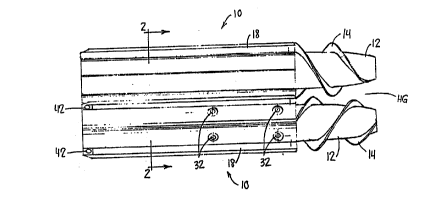
Rouleau broyeur de tiges constitué d'un corps cylindrique ayant six cannelures incorporées. Chaque cannelure comporte un tranchant ayant une surface d'attaque et une surface de fuite. La surface d'attaque comporte une pente vers l'avant d'environ 10° par rapport au plan formé par l'axe longitudinal central du corps cylindrique et le sommet du tranchant respectif. La surface de fuite comporte une pente inverse d'environ 30° par rapport au plan formé par l'axe longitudinal central du corps cylindrique et le sommet du tranchant respectif. Le corps cylindrique comprend deux pièces semi-cylindriques qui sont fixées de part et d'autre de l'arbre d'entraînement d'une récolteuse d'épis de maïs à l'aide de boulons connexes.


Abrégé anglais


A stalk roll comprises a cylindrical shell having six
integral flutes. Each flute is provided with a knife edge
having a leading surface and a trailing surface. The leading
surface has a forward slope of approximately 10~ from the
plane formed by the central longitudinal axis of the
cylindrical shell and the vertex of the respective knife edge.
The trailing surface has a reverse slope of approximately 30~
from the plane formed by the central longitudinal axis of the
cylindrical shell and the vertex of the respective knife edge.
The cylindrical shell comprises two semi-cylindrical pieces
that are clamped about a drive shaft of a corn harvesting head
by associated bolts.

Revendications

Note : Les revendications sont présentées dans la langue officielle dans laquelle elles ont été soumises.


The embodiments of the invention in which an exclusive
property or privilege is claimed are defined as follows:
1. A stalk roll for a corn harvesting header, the stalk
roll comprising:
a cylindrical shell having a central longitudinal axis;
longitudinal integral flutes extending radially from the
shell, the flutes are substantially parallel to the central
longitudinal axis, each flute is provided with a knife edge,
each knife edge has a leading surface and a trailing surface,
the leading surface has a forward slope, the trailing surface
has a reverse slope, the leading surface is steeper than the
trailing surface and forms an acute angle with the trailing
surface; and
means for mounting the shaft to a drive shaft of a corn
harvesting header.
2. A stalk roll as defined by claim 1 wherein the
cylindrical shell is provided with six flutes.
3. A stalk roll as defined by claim 2 wherein the
forward slope of the leading surface is approximately 10° from
the plane formed by the central longitudinal axis and the
vertex of the respective knife edge.
4. A stalk roll as defined by claim 3 wherein the
reverse slope of the trailing surface is approximately 30°
from the plane formed by the central longitudinal axis and the
vertex of the respective knife edge.
5. A stalk roll as defined by claim 2 wherein the
reverse slope of the trailing surface is approximately 30°
from the plane formed by the central longitudinal axis and the
vertex of the respective knife edge.
6. A stalk roll as defined by claim 1 wherein the acute
angle formed by the leading surface and the trailing surface
is approximately 40°.
7. A stalk roll as defined by claim 2 wherein the
cylindrical shell comprises two semi-cylindrical pieces, each
semi-cylindrical piece having three flutes.
8. A stalk roll as defined by claim 7 wherein the means
for mounting comprises at least two bolt holes formed in each
semi-cylindrical piece and associated bolts for clamping the


semi-cylindrical pieces about a drive shaft of a corn
harvesting head.
9. A stalk roll as defined by claim 1 wherein each knife
edge is self-sharpening.
10. A stalk roll as defined by claim 9 wherein the
leading surface is coated with tungsten carbide.
11. A pair of adjoining stalk rolls for a corn header,
the adjoining stalk rolls defining a harvesting gap, each
stalk roll comprising:
a cylindrical shell having a central longitudinal axis;
longitudinal integral flutes extending radially from the
shell, the flutes are substantially parallel to the central
longitudinal axis, each flute is provided with a knife edge,
each knife edge has a leading surface and a trailing surface,
the leading surface has a forward slope, the trailing surface
has a reverse slope, the leading surface is steeper than the
trailing surface and forms an acute angle with the trailing
surface;
whereby the flutes of the pair of adjoining stalk rolls
are offset to one another.
12. A pair of adjoining stalk rolls as defined by claim
11 wherein each knife edge is self-sharpening.
13. A pair of adjoining stalk rolls as defined by claim
12 wherein each of the cylindrical shells is provided with six
flutes.
14. A pair of adjoining stalk rolls as defined by claim
13 wherein the forward slope of each leading surface is
approximately 10° from the plane formed by the central
longitudinal axis and the vertex of the respective knife edge.
15. A pair of adjoining stalk rolls as defined by claim
14 wherein each reverse slope of the trailing surface is
approximately 30° from the plane formed by the central
longitudinal axis and the vertex of the respective knife edge.
16. A pair of adjoining stalk rolls as defined by claim
12 wherein each reverse slope of the trailing surface is
approximately 30° from the plane formed by the central
longitudinal axis and the vertex of the respective knife edge.
17. A pair of adjoining stalk rolls as defined by claim


12 wherein each acute angle formed by the leading surface and
the trailing surface is approximately 40°.
18. A pair of adjoining stalk rolls as defined by claim
12 wherein each cylindrical shell comprises two semi-cylindrical
pieces, each semi-cylindrical piece having three
flutes.

Description

Note : Les descriptions sont présentées dans la langue officielle dans laquelle elles ont été soumises.


2 1 2 3 2 9 4

KNIFE EDGED STALK ROLLS

BACKGROUND OF THE INVENTION -~
1. Field of the Invention: -
The invention is directed to a knife edge stalk roll for
a corn header.
2. Description of the Prior Art:
Modern corn headers are provided with a number of row
crop dividing snouts for directing the corn stalks into
harvesting gaps defined by the snouts. Gathering chains
located in the harvesting gaps draw the stalks towards the
header. Stalk rolls located beneath the gathering chains pull
the stalks rapidly downward returning the stalk to the field.
Two snapper bars are located in the harvesting gap above the
stalk rolls. The snapper bars are spaced from one another to
prevent ears of corn from passing between the bars. The ears
are snapped from the stalk and directed to the combine by the
corn header.
Current residue management rules mandate that the farmer
keep a certain percentage of crop residue on the land to
prevent erosion. With new minimum tillage practices it is
becoming increasingly important to chop up the corn stalks
before returning them to the field so they more easily ~-
decompose. Chopping the stalks into shorter lengths also
provides better clearance for tillage tools. This eliminates -~
the plugging of tillage tools common in longer stalks. A
chopping stalk roll is more aggressive than a conventional
stalk roll. A more aggressive stalk roll reduces trash intake
into the corn head and the combine. Thereby improving overall
combine efficiency and performance.
Case IH corn heads use stalk rolls having four knifes
that are bolted to a solid shaft. Adjoining stalk rolls are
re~istered with one another so that as the stalk rolls are
rotated the opposed knifes come into contact with opposite
sides of the stalk at the same general location thereby
cutting the stalk into smaller pieces. It is important that
the blades are correctly registered with one another, and that ~
the blades are correctly spaced from one another. ;~-


: ~'


.. ". ' ' . ~ . . - .. ' ' '

2123294
U.S. Patents 4,845,930 an~ 5,040,361 disclose stalk rolls
having interleaved canted blades for chopping the corn stalks.
U.S. Patent 4,233,804 ~iscloses a stalk roll having six flutes
in which three of the flutes are radially aligned with the
central longitudinal axis of the stalk roll. Other chopping
stalk rolls are disclosed in U.S. Patents 3,304,702 and
4,974,402.
Semi-cylindrical husking rolls have been clamped onto
drive shafts by bolts as disclosed in U.S. Patents 2,469,687,
2,538,965 and 3,101,720.
SUMMARY
It is an object of the present invention to provide a
simple stalk roll structure that effectively and efficiently
chops corn stalks during harvesting.
It is a feature of the present invention that each stalk
roll is provided with six outwardly extending integral flutes.
Each flute has a knife edge that is provided with a leading
surface and a trailing surface. A respective knife edge
extends the length of each flute. The leading surface of the
knife edge has a ten degree forward slope, whereas the
trailing surface has a thirty degree reverse slope from a ;
radial plane extending through the vertex of the knife edge
and the central longitudinal axis of the stalk roll.
Therefore the leading surface is steeper than the trailing
surface of each knife edge.
The stalk rolls of the present invention are designed to
be mounted to drive shafts located on either side of the
harvesting gap in a corn head. The drive shafts rotate the
- stalk rolls in opposite directions to pull the corn stalks ;~
'~ 30 downwardly through the harvesting gap so that the ears of corn
are snapped off by the snapper bars located above the stalk
rolls. The radially extending flutes of the stalk rolls
' located in a harvesting gap are interleaved with one another.
~ It is another feature of the present invention that the
!~' 35 stalk roll comprises a cylindrical shell formed by two semi-
' cylindrical pieces that are clamped about a drive shaft.


,

''':

21~3294
,
Bolts extend between the two semi-cylindrical pieces to
pull the pieces together thereby clamping the stalk rolls to
the drive shaft.
BRIEF DESCRIPTION OF THE DRAWINGS
Figure 1 is a top view of the stalk rolls.
Figure 2 is a cross sectional view taken along line 2--2
in Figure 1.
Figure 3 is an exploded view of the stalk rolls.
DETAILED DESCRIPTION
Each harvesting gap HG on a corn harvesting header is
provided with two stalk rolls arranged parallel to one
another. The two stalk rolls 10 are provided with noses 12
having helical flighting 14. Immediately behind the noses are
cylindrical shells 16 having six integral longitudinal flutes
18. Each flute is provided with a knife edge 20. The knife
edges 20 are substantially parallel to the central
longitudinal axis A of the cylindrical shell 16.
Each cylindrical shell comprises two semi-cylindrical
pieces 24 and 26 that are bolted to the stalk roll drive shaft
28. The bolt holes and bolts form a means for mounting the
stalk roll to the drive shaft and are described in greater
detail below. ::~
' Each semi-cylindrical piece is cast having three integral -
flutes. The flutes are then machined to define the knife -~;
edges. Each knife edge has a leading surface 29 and a
trailing surface 31 that form an acute angle between them of -
approximately 40~. The leading surface is a forward sloping
surface, sloping approximately 10~ to the radial plane defined
by the central longitudinal axis of the cylindrical shell and
the vertex of the knife edge. The trailing surface is a
reverse sloping surface, slopes approximately 30~ to the
radial plane defined by the central longitudinal axis and the
vertex of the knife edge. ~
Tungsten carbide is applied to the leading edges to make ~ -
the knife edges self-sharpening. As illustrated in Figure 2
the flutes of the adjoining stalk rolls are offset
(interleaved) to one another.


.,
.:
. ~ .

2123294
Figure 3 better illustrates the mounting structure. Each
shell is provided with two inwardly extending annular ridges
30 having bolt holes 32. Short bolts 34 are screwed into
holes 32 and engage bolt holes 36 located on an intermediate
drive shaft 38. Long bolts 40 are screwed into holes 42 for
clamping the cylindrical shell together.
The intermediate drive shaft is clamped to the main drive
shaft by bolts 44. In addition two pins 46 and 48 prevent
relative rotation between the intermediate drive shaft and the
main drive shaft. -
The invention should not be limited by the above-
described embodiment, but should be limited solely by the -
claims that follow. -


.. ,~. ... . . . .. .... . . . .. ....

Dessin représentatif
Une figure unique qui représente un dessin illustrant l'invention.
États administratifs

Pour une meilleure compréhension de l'état de la demande ou brevet qui figure sur cette page, la rubrique Mise en garde , et les descriptions de Brevet , États administratifs , Taxes périodiques et Historique des paiements devraient être consultées.

États administratifs

Titre Date
Date de délivrance prévu 1997-10-07
(22) Dépôt 1994-05-10
Requête d'examen 1994-05-10
(41) Mise à la disponibilité du public 1994-11-12
(45) Délivré 1997-10-07
Expiré 2014-05-12

Historique d'abandonnement

Il n'y a pas d'historique d'abandonnement

Historique des paiements

Type de taxes Anniversaire Échéance Montant payé Date payée
Le dépôt d'une demande de brevet 0,00 $ 1994-05-10
Enregistrement de documents 0,00 $ 1994-11-04
Taxe de maintien en état - Demande - nouvelle loi 2 1996-05-10 100,00 $ 1996-05-10
Taxe de maintien en état - Demande - nouvelle loi 3 1997-05-12 100,00 $ 1997-05-09
Taxe finale 300,00 $ 1997-05-29
Taxe de maintien en état - brevet - nouvelle loi 4 1998-05-11 100,00 $ 1998-05-08
Taxe de maintien en état - brevet - nouvelle loi 5 1999-05-10 150,00 $ 1999-05-07
Taxe de maintien en état - brevet - nouvelle loi 6 2000-05-10 150,00 $ 2000-05-09
Taxe de maintien en état - brevet - nouvelle loi 7 2001-05-10 150,00 $ 2001-05-09
Taxe de maintien en état - brevet - nouvelle loi 8 2002-05-10 150,00 $ 2002-05-09
Taxe de maintien en état - brevet - nouvelle loi 9 2003-05-12 150,00 $ 2003-05-09
Taxe de maintien en état - brevet - nouvelle loi 10 2004-05-10 250,00 $ 2004-04-21
Taxe de maintien en état - brevet - nouvelle loi 11 2005-05-10 250,00 $ 2005-04-20
Taxe de maintien en état - brevet - nouvelle loi 12 2006-05-10 250,00 $ 2006-04-18
Taxe de maintien en état - brevet - nouvelle loi 13 2007-05-10 250,00 $ 2007-04-17
Taxe de maintien en état - brevet - nouvelle loi 14 2008-05-12 250,00 $ 2008-04-17
Taxe de maintien en état - brevet - nouvelle loi 15 2009-05-11 450,00 $ 2009-04-17
Taxe de maintien en état - brevet - nouvelle loi 16 2010-05-10 450,00 $ 2010-04-19
Taxe de maintien en état - brevet - nouvelle loi 17 2011-05-10 450,00 $ 2011-04-18
Taxe de maintien en état - brevet - nouvelle loi 18 2012-05-10 450,00 $ 2012-04-17
Taxe de maintien en état - brevet - nouvelle loi 19 2013-05-10 450,00 $ 2013-04-17
Titulaires au dossier

Les titulaires actuels et antérieures au dossier sont affichés en ordre alphabétique.

Titulaires actuels au dossier
DEERE & COMPANY
Titulaires antérieures au dossier
ADAMS, BONNIE D.
CHRISTENSEN, TIMOTHY F.
SANDAU, JERRY ALAN
Les propriétaires antérieurs qui ne figurent pas dans la liste des « Propriétaires au dossier » apparaîtront dans d'autres documents au dossier.
Documents

Pour visionner les fichiers sélectionnés, entrer le code reCAPTCHA :


Pour visualiser une image, cliquer sur un lien dans la colonne description du document. Pour télécharger l'image (les images), cliquer l'une ou plusieurs cases à cocher dans la première colonne et ensuite cliquer sur le bouton "Télécharger sélection en format PDF (archive Zip)" ou le bouton "Télécharger sélection (en un fichier PDF fusionné)".

Liste des documents de brevet publiés et non publiés sur la BDBC .

Si vous avez des difficultés à accéder au contenu, veuillez communiquer avec le Centre de services à la clientèle au 1-866-997-1936, ou envoyer un courriel au Centre de service à la clientèle de l'OPIC.


Description du
Document 
Date
(yyyy-mm-dd) 
Nombre de pages   Taille de l'image (Ko) 
Page couverture 1995-04-14 1 69
Abrégé 1995-04-14 1 38
Revendications 1995-04-14 3 170
Dessins 1995-04-14 2 109
Description 1995-04-14 4 250
Page couverture 1997-10-01 1 49
Dessins représentatifs 1997-10-01 1 11
Taxes 1997-05-09 1 39
Taxes 1996-05-10 1 34
Correspondance de la poursuite 1994-05-10 3 122
Correspondance reliée aux formalités 1997-05-29 1 35