Sélection de la langue

Search

Sommaire du brevet 2123601 

Énoncé de désistement de responsabilité concernant l'information provenant de tiers

Une partie des informations de ce site Web a été fournie par des sources externes. Le gouvernement du Canada n'assume aucune responsabilité concernant la précision, l'actualité ou la fiabilité des informations fournies par les sources externes. Les utilisateurs qui désirent employer cette information devraient consulter directement la source des informations. Le contenu fourni par les sources externes n'est pas assujetti aux exigences sur les langues officielles, la protection des renseignements personnels et l'accessibilité.

Disponibilité de l'Abrégé et des Revendications

L'apparition de différences dans le texte et l'image des Revendications et de l'Abrégé dépend du moment auquel le document est publié. Les textes des Revendications et de l'Abrégé sont affichés :

  • lorsque la demande peut être examinée par le public;
  • lorsque le brevet est émis (délivrance).
(12) Brevet: (11) CA 2123601
(54) Titre français: SERINGUE
(54) Titre anglais: SYRINGE
Statut: Réputé périmé
Données bibliographiques
(51) Classification internationale des brevets (CIB):
  • A61M 5/28 (2006.01)
  • A61J 1/00 (2006.01)
  • A61M 5/31 (2006.01)
(72) Inventeurs :
  • REYNOLDS, DAVID L. (Canada)
(73) Titulaires :
  • DUOJECT MEDICAL SYSTEMS INC. (Canada)
(71) Demandeurs :
  • DUOJECT MEDICAL SYSTEMS INC. (Canada)
(74) Agent: BERESKIN & PARR
(74) Co-agent:
(45) Délivré: 2003-06-10
(86) Date de dépôt PCT: 1992-11-13
(87) Mise à la disponibilité du public: 1993-05-27
Requête d'examen: 1999-11-12
Licence disponible: S.O.
(25) Langue des documents déposés: Anglais

Traité de coopération en matière de brevets (PCT): Oui
(86) Numéro de la demande PCT: PCT/CA1992/000495
(87) Numéro de publication internationale PCT: WO1993/009825
(85) Entrée nationale: 1994-05-13

(30) Données de priorité de la demande:
Numéro de la demande Pays / territoire Date
791,399 Etats-Unis d'Amérique 1991-11-14

Abrégés

Abrégé anglais


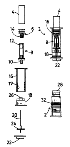
A prefilled syringe system is provided for two component pharmaceuticals,
which is a combination of a first subassembly consisting of a capped
bottomless
pharmaceutical vial (2) containing a first component and closed at its bottom
end
by a piston (32) which can be connected to a plunger (16) and a second
subassem-
bly (3) consisting of a shell (4) containing a second component and closed by
a fur-
ther piston (6) and located in telescopable relationship with the plunger, a
cap (18)
which can be forced onto the cap (36) of the bottomless vial, and a double
ended
noodle (320) or a functionally equivalent cannula assembly which is caused to
pierce both pistons as the assemblies are connected by forcing the cap (18)
onto the
bottomless vial, thus placing the vials in communication. The shell vial (4)
is
pressed towards the bottomless vial (2) to express its contents into the
latter, and
the plunger (16) and shell vial {4) are then removed so that the cap (18) and
needle
(20) are left connected to the bottomless vial (2) and the plunger (16) may be
con-
nected to the piston (32) of the bottomless vial to convert it into a syringe.
The shell
vial may telescope either over or within the plunger. In the first case, the
plunger
ads to operate the piston of the shell vial during expression of its contents,
whereas
in the latter case a separate component (8) is required for this purpose.

Revendications

Note : Les revendications sont présentées dans la langue officielle dans laquelle elles ont été soumises.


-6-

Claims:

1. A prefilled syringe system for two component
pharmaceuticals, characterized by a combination of first and
second subassemblies, of which the first subassembly
comprises a bottomless pharmaceutical vial comprising a first
component having a filling neck, a penetrable closure
retained on said neck by a first annular cap, and an open
bottom end hermetically closed by a first piston with a
downwardly facing coupling configuration within the vial, and
the second subassembly comprises a shell vial comprising a
second fluid component and having an open end closed by a
second piston, a tubular plunger concentric and in
telescoping relationship with the shell vial, the plunger
having a coupling means at one end for subsequent coupling of
the plunger to the coupling configuration of said first
piston, a second cap releasably connected to said plunger
which can be force fitted to said first cap, and cannula
means penetrating both said penetrable closure and said
second piston to place said bottomless vial and said shell
vial in fluid communication through said cannula means when
said first cap is forced onto said second cap, whereby the
fluid from the shell vial is transferred to the bottomless
vial upon telescoping said shell vial relative to said
plunger.

2. A syringe system according to claim 1, characterized in
that the shell vial is of a diameter to telescope into said
plunger, and adaptor means are provided in said second
subassembly extending between said second cap and a coupling
configuration on said second piston to maintain the position
of the latter during telescoping of the shell vial relative
to the plunger.


3. A syringe system according to claim 1, characterized in
that the shell vial is of a diameter to telescope around said
plunger, and said coupling means on the plunger for coupling
to the coupling configuration of the first piston are
initially coupled to coupling configuration on the second
piston.

4. A syringe according to claim 3, characterized in that
the components of the second subassembly are assembled within
a tubular housing, and the shell vial is a press fit within
the tubular housing.

5. A syringe system according to any one of claims 1-4,
characterized in that the cannula means is a double ended
needle, with a flange to control its longitudinal position
received within the second cap.

6. A prefilled syringe system for two component
pharmaceuticals, characterized by a combination of first and
second subassemblies, of which the first subassembly
comprises a bottomless pharmaceutical vial comprising a first
fluid component having a filling neck, a penetrable closure
retained on said neck by a first annular cap, and an open
bottom end hermetically closed by a first piston with a
downwardly facing coupling configuration within the vial, and
the second subassembly comprises a shell vial comprising a
second component and having an open end closed by a second
piston, a tubular plunger concentric and in telescoping
relationship with the shell vial, the plunger having a
coupling means at one end for subsequent coupling of the
plunger to the coupling configuration of said first piston, a
second cap releasably connected to said plunger which can be
force fitted to said first cap, and cannula means penetrating


-8-

both said penetrable closure and said second piston to place
said bottomless vial and said shell vial in fluid
communication through said cannula means when said first cap
is forced onto said second cap, whereby the first component
from the shell vial is transferred to the bottomless vial
upon telescoping said shell vial relative to said plunger.

7. A syringe system according to claim 6, characterized in
that the shell vial is of a diameter to telescope into said
plunger, and adaptor means are provided in said second
subassembly extending between said second cap and a coupling
configuration on said second piston to maintain the position
of the latter during telescoping of the shell vial relative
to the plunger.

8. A syringe system according to claim 6, characterized in
that the shell vial is of a diameter to telescope around said
plunger, and said coupling means on the plunger for coupling
to the coupling configuration of the first piston are
initially coupled to coupling configuration on the second
piston.

9. A syringe according to claim 8, characterized in that
the components of the second subassembly are assembled within
a tubular housing, and the shell vial is a press fit within
the tubular housing.

10. A syringe system according to any one of claims 6-9,
characterized in that the cannula means is a double ended
needle, with a flange to control its longitudinal position
received within the second cap.

Description

Note : Les descriptions sont présentées dans la langue officielle dans laquelle elles ont été soumises.


CA 02123601 2002-09-05
. _ 1 _
SYRINGE
TECHNICAL FIELD
This invention relates to prefilled syringe systems
for the packaging of pharmaceutical preparations in dosage
form, and more particularly to systems in which two
components of a preparation, one of which is normally a
diluent or solvent, must be stored separately and only
admixed immediately prior to administration.
BACKGROUND ART
Our United States Patent No. 5,137,511 describes
several syringe systems for the packaging of two component
pharmaceutical preparations, of which the system shown in
Figures 11 and 12 is presently the most preferred. This
system stores solvent or diluent component in a specially
formed capsule which is described in detail in that patent.
Shell vials are however a well known and widely
available packaging for pharmaceutical diluents. A shell
vial differs from a conventional pharmaceutical or serum vial
in that it has no neck. Instead the top of the vial is of
the same diameter as the remainder of the cylindrical side
wall of the vial, and is closed by a piston quite similar to
that utilized by the present applicant to close the bottom of
its bottomless vial as described in U.S. Patent No.
5,137,511.
DISCLOSURE OF INVENTION
I have now found that the construction shown in
this patent can be advantageously modified to utilize known
shell vials in place of the capsule.
According to the invention, a prefilled syringe
system for two component pharmaceuticals is provided, as set
forth in the appended claims 1-10.

WO 93/09825 PCT/CA92/00495
2123601
BRIEF DESCRIPTION OF DRAWINGS
Preferred embodiments of the invention are
described with reference to the accompanying drawa.ngs, in
which:
Figures lA-lI are elevations illustrating
successive stages in the assembly and preparation of use of
a first embodiment of the invention, it being assumed for
ease in illustration that most components other than those
of rubber or metal are transparent; and
Figures 2A-2G are elevations illustrating
successive stages in the assembly and preparation for use
of a second embodiment of the invention.
BEST MODES FOR CARRYING OUT THE INVENTION
Figure 1A shows an exploded view of the components
of a separately assembled and sterilized unit 3 (see Figure
1B) for use in conjunction with a filled and capped vial 2
generally similar to that shown in Figure 12 of U.S. Patent
No. 5,137,511. The unit 3 comprises a shell vial having a
cylindrical body 4 closed at one end, and a piston 6
closing its other end to enclose a quantity of
pharmaceutical diluent. A moulded plastic tubular adaptor
component 8 has a tubular connector 10 at one end similar
to the connector element 70 of U.S. Patent No. 5,137,511,
and an internal thread 12 within its other end forms a
coupling engaged with an external thread on a extension 14
forming a coupling configuration on the piston 6. A
tubular plunger 16 has an internal thread i7 which can
provide a coupling to an integral extension or other
coupling configuration on a piston 32 of the vial 2. This
plunger and a cap 18 are similar to corresponding parts
shown in the U.S. patent. The unit further includes a
cannula needle 20, and a protective cap 22 which closes the
open end of the cap 18 to maintain sterility and provide
protection of the needle during storage. The cap 22 is

i
CA 02123601 2002-07-18
- 3 -
removed immediately before use ( see Figure 1C ) . The needle


20 is of the double ended type, and is located beneath the


cap 18 by a flange 24. A connector 26 on the cap engages the


connector 10 on the adaptor component 8 in the same way as


the connector 27 engages the connector 70 in Figure 12 of


U.S. Patent No. 5,137,511, so that one end of the needle 20


passes through the adaptor towards the piston extension 14,


as seen in Figure 1B.


After the cap 22 has been removed ( Figure 1C ) , as


well as a flip-off protective cover 28 on the cap 30 of the


vial 2 (Figure 1D), which protects a rubber closure of the


vial held in place by the cap 30 ( Figure 1E ) , the unit is
3


pressed onto the vial 2 (Figure 1F) so that the cap 18 is


pressed over the cap 30 of the vial 2 so that the lower end


of the needle 20 pierces rubber closure of the vial 2. At


the same time, the flange 24 is pressed upwardly within the


cap 18 and causes the upper end of the needle 20 to penetr ate


a septum within the piston 6.


The shell vial 4 is then pressed downwardly (Fig ure


1F) expelling its contents through the needle 20 into the


vial 2. If necessary, the piston 32 within the vial 2 is


positioned higher in the vial than normal so that it can be


displaced downwardly to make room for the contents of via l
4


(see Figure 1G).


At this point, the assembly 3, with the except ion


of the cap 18 and the needle 20, is pulled away from the v ial


2 by gripping the plunger 16 leaving the cap and needle in


place on the vial (Figure 1G). The thread 17 of plunger 16


is then screwed onto the piston 32 of the vial 2 (Figure 1H)


to form a syringe 34 (Figure 1I).


In the embodiment just described, the shell vial is


dimensioned so as to fit within the tubular plunger. An


WO 93/09825 PCT/CA92/00495
~~~~,
21~3~41
- 4 -
alternative embodiment is shown in Figures 2A-G in which
the shell vial 4 is dimensioned so that the tubular plunger
16 has an external diameter less than its internal
diameter. The same reference numerals are used_to denote
those components of this embodiment which are similar to
those of the previous embodiment, and only the differences
will be described. In this instance, the plunger 16
fulfils the functions of the adaptor 8, the screw threads
on extensions of the pistons 6 and 32 being similar except
that the thread 14 on piston 6 may be longer. The plunger
16 is a press fit on the connector 26 on the cap 18, which
in this case is formed with a skirt 36 which fits over the
top portion of the vial 2 and also provides a finger grip
38. The entire unit 3 (see Figure 2C) is assembled into a
tubular sleeve 40 (Figure 2B) which together with the cap
22 maintains sterility of the.unit during storage, and also
facilitates preparation of the syringe. The vial 4 is a
press fit within the upper end of the sleeve 40. After
removal of the cap 22, the unit 3 is applied to the vial
(Figure 2D) as in the previous embodiment, and the sleeve
40 is pulled downwardly (Figure 2E). As before, this
forces the cap 18 onto the cap 30 of the vial, causing the
needle 20 to pierce both the closure of the vial 2 and the
piston 6 of the shell vial 4, and further downward movement
of the sleeve 40 forces the contents of the shell vial into
the vial 2. At this point the sleeve 40 is rotated to
unscrew the piston 6 of the shell vial 4 from the plunger
16 (Figure 2F) which is then transferred to the piston 32
to complete the syringe.
It should be understood that the sleeve 40 could be
omitted, although it is a convenience for packaging and
manipulating the syringe, in which case the vial 4 would be
manipulated directly rather than through the sleeve 40.

WO 93/09825 PCT/CA92/00495
2~~360:1
- 5 -
Variations >:~ the above embodii .=nts are p~ssible.
For some applications of the syringe, it may be desired to
replace the needle 20 by some other cannula arrangement
when the syringe is used, in which case a single ended
needle may be located in the assembly 3 so that it will be
forced upwardly as the cap 18 is forced onto the vial 2
(the cap in this case will have an internal cannula to
pierce the closure of the vial), but will be retained
within the shell vial when the latter is removed during
preparation of the syringe. If a double ended needle 30 is
used, in combination with a cannula, venting of the vial 2
to permit escape of air displaced by the contents of the
shell vial 4 becomes possible, in a manner similar to that
shown in Figure 16 of U.S. Patent No. 5,137,511.

Dessin représentatif
Une figure unique qui représente un dessin illustrant l'invention.
États administratifs

Pour une meilleure compréhension de l'état de la demande ou brevet qui figure sur cette page, la rubrique Mise en garde , et les descriptions de Brevet , États administratifs , Taxes périodiques et Historique des paiements devraient être consultées.

États administratifs

Titre Date
Date de délivrance prévu 2003-06-10
(86) Date de dépôt PCT 1992-11-13
(87) Date de publication PCT 1993-05-27
(85) Entrée nationale 1994-05-13
Requête d'examen 1999-11-12
(45) Délivré 2003-06-10
Réputé périmé 2005-11-14

Historique d'abandonnement

Il n'y a pas d'historique d'abandonnement

Historique des paiements

Type de taxes Anniversaire Échéance Montant payé Date payée
Le dépôt d'une demande de brevet 0,00 $ 1994-05-13
Taxe de maintien en état - Demande - nouvelle loi 2 1994-11-14 100,00 $ 1994-10-28
Enregistrement de documents 0,00 $ 1994-11-18
Taxe de maintien en état - Demande - nouvelle loi 3 1995-11-13 100,00 $ 1995-10-27
Taxe de maintien en état - Demande - nouvelle loi 4 1996-11-13 100,00 $ 1996-08-12
Taxe de maintien en état - Demande - nouvelle loi 5 1997-11-13 150,00 $ 1997-08-12
Taxe de maintien en état - Demande - nouvelle loi 6 1998-11-13 150,00 $ 1998-08-19
Taxe de maintien en état - Demande - nouvelle loi 7 1999-11-15 150,00 $ 1999-08-30
Requête d'examen 400,00 $ 1999-11-12
Taxe de maintien en état - Demande - nouvelle loi 8 2000-11-13 150,00 $ 2000-10-23
Taxe de maintien en état - Demande - nouvelle loi 9 2001-11-13 150,00 $ 2001-10-17
Taxe de maintien en état - Demande - nouvelle loi 10 2002-11-13 200,00 $ 2002-10-22
Taxe finale 300,00 $ 2003-03-21
Taxe de maintien en état - brevet - nouvelle loi 11 2003-11-13 200,00 $ 2003-10-29
Titulaires au dossier

Les titulaires actuels et antérieures au dossier sont affichés en ordre alphabétique.

Titulaires actuels au dossier
DUOJECT MEDICAL SYSTEMS INC.
Titulaires antérieures au dossier
REYNOLDS, DAVID L.
Les propriétaires antérieurs qui ne figurent pas dans la liste des « Propriétaires au dossier » apparaîtront dans d'autres documents au dossier.
Documents

Pour visionner les fichiers sélectionnés, entrer le code reCAPTCHA :


Pour visualiser une image, cliquer sur un lien dans la colonne description du document. Pour télécharger l'image (les images), cliquer l'une ou plusieurs cases à cocher dans la première colonne et ensuite cliquer sur le bouton "Télécharger sélection en format PDF (archive Zip)" ou le bouton "Télécharger sélection (en un fichier PDF fusionné)".

Liste des documents de brevet publiés et non publiés sur la BDBC .

Si vous avez des difficultés à accéder au contenu, veuillez communiquer avec le Centre de services à la clientèle au 1-866-997-1936, ou envoyer un courriel au Centre de service à la clientèle de l'OPIC.


Description du
Document 
Date
(yyyy-mm-dd) 
Nombre de pages   Taille de l'image (Ko) 
Page couverture 2003-05-06 2 50
Page couverture 1995-07-29 1 16
Abrégé 1995-07-29 1 65
Description 2002-07-18 5 227
Revendications 2002-07-18 3 139
Revendications 1995-07-29 2 75
Dessins 1995-07-29 4 83
Description 1995-07-29 5 230
Description 2002-09-05 5 224
Dessins représentatifs 2002-09-12 1 5
Dessins représentatifs 1998-07-23 1 6
Correspondance 2003-03-21 1 40
Taxes 2003-10-29 1 33
Taxes 2002-10-22 1 35
Taxes 1997-08-12 1 33
Correspondance 2002-07-18 3 85
Poursuite-Amendment 2002-07-18 8 370
Correspondance 2002-09-05 2 76
Correspondance 2002-08-22 1 12
Correspondance 2002-08-22 1 19
Taxes 2001-10-17 1 30
Taxes 1998-08-19 1 36
Poursuite-Amendment 2002-01-22 2 55
Cession 1994-05-13 8 307
PCT 1994-05-13 10 318
Poursuite-Amendment 1999-11-12 2 53
Taxes 1999-08-30 1 27
Taxes 2000-10-23 1 31
Taxes 1996-08-12 1 36
Taxes 1995-10-27 1 35
Taxes 1994-10-28 1 33