Sélection de la langue

Search

Sommaire du brevet 2124840 

Énoncé de désistement de responsabilité concernant l'information provenant de tiers

Une partie des informations de ce site Web a été fournie par des sources externes. Le gouvernement du Canada n'assume aucune responsabilité concernant la précision, l'actualité ou la fiabilité des informations fournies par les sources externes. Les utilisateurs qui désirent employer cette information devraient consulter directement la source des informations. Le contenu fourni par les sources externes n'est pas assujetti aux exigences sur les langues officielles, la protection des renseignements personnels et l'accessibilité.

Disponibilité de l'Abrégé et des Revendications

L'apparition de différences dans le texte et l'image des Revendications et de l'Abrégé dépend du moment auquel le document est publié. Les textes des Revendications et de l'Abrégé sont affichés :

  • lorsque la demande peut être examinée par le public;
  • lorsque le brevet est émis (délivrance).
(12) Brevet: (11) CA 2124840
(54) Titre français: DISPOSITIF D'ANCRAGE
(54) Titre anglais: ANCHORING MEMBER
Statut: Périmé
Données bibliographiques
(51) Classification internationale des brevets (CIB):
  • A61B 17/58 (2006.01)
  • A61B 17/70 (2006.01)
  • A61B 17/86 (2006.01)
(72) Inventeurs :
  • HARMS, JURGEN (Allemagne)
  • SHUFFLEBARGER, HARRY L. (Etats-Unis d'Amérique)
  • BIEDERMANN, LUTZ (Allemagne)
(73) Titulaires :
  • BIEDERMANN TECHNOLOGIES GMBH & CO. KG (Allemagne)
(71) Demandeurs :
(74) Agent: GOUDREAU GAGE DUBUC
(74) Co-agent:
(45) Délivré: 1998-08-25
(86) Date de dépôt PCT: 1993-10-08
(87) Mise à la disponibilité du public: 1994-04-28
Requête d'examen: 1994-07-25
Licence disponible: S.O.
(25) Langue des documents déposés: Anglais

Traité de coopération en matière de brevets (PCT): Oui
(86) Numéro de la demande PCT: PCT/EP1993/002756
(87) Numéro de publication internationale PCT: WO1994/008527
(85) Entrée nationale: 1994-05-31

(30) Données de priorité de la demande:
Numéro de la demande Pays / territoire Date
P 42 34 118.3 Allemagne 1992-10-09

Abrégés

Abrégé français

Élément d'ancrage comportant un axe fileté (2) destiné à être fixé à un os, et une tête (3) venant en prise avec une tige (10), la tête présentant une coupe transversale en forme de U et venant en contact avec l'axe fileté (2) par sa partie inférieure (5); la tête comporte en outre deux pattes (6 et 7) définissant un passage (4) pour loger la tige (10). Les pattes (6 et 7) comportent un filetage intérieur (8) sur toute leur longueur. Un organe de fixation (11) couplé à un organe complémentaire (12) entourent les pattes. Afin de permettre l'utilisation non seulement de tiges droites, mais aussi de tiges incurvées pour adapter l'appareil aux conditions spécifiques de la colonne vertébrale à traiter, les pattes sont dotées d'un filetage extérieur (9) qui vient en coopération avec le filetage intérieur de l'organe complémentaire (12). L'organe de fixation (11) est doté d'un filetage qui vient en coopération avec le filetage intérieur (8) permettant de visser celui-ci.


Abrégé anglais


An anchoring member is provided which comprises a shaft 2
to be fastened to a bone and a head 3 for connection with a
rod 10, the head having a substantially U-shaped cross-section
and being connected with the shaft 2 at the base 5
thereof, the head further comprising two free legs 6, 7
defining a channel 4 for receiving the rod 10. The free
legs 6, 7 are provided with an internal thread 8 extending
in direction of the legs. A fastening member 11 and a
member 12 embracing the legs at the outside thereof are
provided. In order to allow not only straight rods, but
also curved rods to be received and thus to allow an
individual adaptation to the conditions of the spinal
column to be treated the free legs have an external thread
9 and the member 12 has an internal thread cooperating
therewith. The fastening member 11 comprises a thread
cooperating with the internal thread 8 to allow the
fastening member to be screwed in.


Revendications

Note : Les revendications sont présentées dans la langue officielle dans laquelle elles ont été soumises.


- 7 -

CLAIMS

1. Anchoring member with a shaft (2, 16) to be fastened to
a bone and a head (3) for connection with a rod (10, 15),
the head having a substantially U-shaped cross-section
which has its base (5) connected to the shaft (2, 16) and
comprises two free legs (6, 7) defining a channel for
receiving the rod (10, 15),
wherein the legs (6, 7) comprise an internal thread (8) and
an external thread (9),
and with a member (12) embracing the legs (6, 7) at their
outer side and having an internal thread cooperating with
the external thread, and with a fastening member (11)
having a thread cooperating with the internal thread (8) of
the legs,
characterized in that the base (5) of the U-shaped recess
(4) has a curved portion in a direction perpendicular to
the U-shaped cross-section.

2. Anchoring member according to claim 1,
characterized in that the rims (18, 19) of the base (5) are
formed to slope outwardly downwards towards the shaft (2,
16).

3. Anchoring member according to claims 1 or 2,
characterized in that a recess (17) is provided in the base
(5) of the channel coaxial to the first internal thread
(8).

4. Anchoring member according to any of the claims 1 to 3,
characterized in that the curvature comprises a depressed
portion towards the center.

5. Anchoring member according to claim 4,
characterized in that the curvature comprises a respective


- 8 -

projecting cambered portion (21, 22) spaced from the
center.

6. Anchoring member according to claim 4,
characterized in that the spacing of a cambered portion
(21, 22) substantially corresponds to the center (23)
between the radius of the internal thread (8) and that of
the external thread (11).

Description

Note : Les descriptions sont présentées dans la langue officielle dans laquelle elles ont été soumises.

21~84~


ANCHORING MEMBER


The invention relates to an anchoring member with a shaft
to be fastened to a bone and a head for connection with a -~
rod, the head having a substantialiy U-shaped cross-section ~'
which has its base connected to the shaft and comprises two
free legs defining a channel for receiving the rod, wherein -
the legs comprise an internal thread and an external
thread, and with a member embracing the legs at their outer
side and having an internal thread cooperating with the
external thread, and with a fastening member having a
thread cooperating with the internal thread of the legs.
Such an anchoring member is known from document
EP-A-0,487,830. The rod comprises a triangular cross-
section and serves as a restraint from torsional motions.
The longitudinal stabilisation proper is provided by plates
which are curved corresponding to the intended shape cor-
rection. By nature the plates are comparatively space-
consuming. Further, the base between both legs is formed
flat in longitudinal direction of the slit. In a practical
application there is a considerable repeated alternating
stress caused by the forces acted onto the rod. Hence, the
rods tend to break after some time at the edges of the slit
base.
' ~'
It is the object of the invention to form the anchoring
member in such a -nner that the size of the anchor can be
reduced and the anchor resists to higher conti~uous '
stresses. This is of particular importance, because such
anchoring members and the rods to be connected thereto are
used as components for correction implants for the human
3S spinal column and small dimensions and an unlLmited
stability under load are therefore desired.

212~8~0

-- 2

This object is achieved in that the base of the U-shaped
recess has a curved portion in a direction perpendicular
to the U-shaped cross-section. As a consequence, round rods
which are bent corresponding to the form correction can be
used in place of the plate members for the form correction
proper, because even bent rods can be perfectly fastened
within the anchoring members. Moreover, the stability under
continuous load is considerably increased for straight
rods, but in particular also for curved rods.
Further features and advantages of the invention will be
evident from the description of embodiments with reference
to the drawings.

In the drawings:

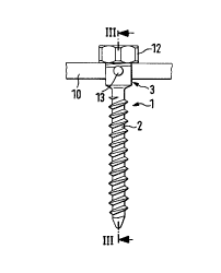
Fig. l shows a side view of a first embodiment of the
anchoring member;

Fig. 2 is a front view of the apparatus shown in Fig. 1;

Fig. 3 shows a section along line III-III in Fig. 1;

Fig. 4 shows a section along line IV-IV in Fig. 2;
Fig. 5 i8 a side view of a second embodiment;

Fig. 6 6hows a section along the plane of symmetry of a
modified embodiment in exploded representation;
Fig. 8 corresponds to Fig. 7 with mounted straight rod;

Fig. 9 shows the same embodiment with a conve~ly curved
rod; and
Fig. 10 shows the same embodiment with a concavely curved
rod.

2~2~a
- 3 -


The anchoring member shown in Fig. 1 comprises a screw 1 to
be introduced into a spinal column and having a threaded
shaft 2 and a head 3. The head 3 comprises a U-shaped
recess 4 which is symmetric with respect to the central
axis of the threaded shaft 2 and which has a base 5
directed towards the threaded shaft 2. The lateral wall of
the head defining the U-shaped recess 4 is formed by free
legs 6, 7. As best shown in Figs. 3, 4 and 5 a bore which
is coaxial with the center axis of the threaded shaft 2 and
has an internal thread 8 is provided in the interior of the
channel. The head 3 itself is cylindrical and comprises an
external thread 9 at the region of the free legs 6, 7, as ~ ~
best shown in Fig. 4. ~;
In order to allow a rod to be anchored by means of this
screw a fastening member 11 formed as a threaded bolt is
provided. The fastening member 11 comprises an external
thread cooperating with the internal thread 8 for screwing ~
into the U-shaped recess 4. The fastening member has a slit -
or any other suitable recess for engagement of a screw
driver formed at its face opposite to the base 5. Further,
a surrolln~ ng member embracing both U-shaped legs 6, 7 at
their outer side is formed as a spigot 12 having a thread
which cooperates with the external thread 9. The sense of
rotation of the internal thread 8 and of the associated
fastening member 11 is opposite to that of the external
thread 9 and of the spigot 12. As best shown in Fig. 3 the
base 5 of the U-shaped recess has a radius which is larger
than the radius of the rod 10 to be received therein by
such a slight amount only that the rod may easily be in-
serted into the U-shaped recess and removed therefrom,
resp. Both the-internal thread 8 and the external thread 9
extend as far downwards, i.e. in direction of the basis 5,
that the projection onto the axis of symmetry is spaced
from the base 5 by a distance which is smaller than the ~ -
diameter of the rod 10 to be received. ~
.

2~2~0
'
-- 4 --


In the embodiment shown in Fig. 5 the head is connected to
a shaft formed as a hook 16 rather than to a threaded
shaft. This shaft as well serves for connection to a member
of the spinal column wherein the hook is introduced into
the arch of a vertebra.

In the embodiment shown in Fig. 6 the base of the U-shaped
recess comprises a countersunk hole 17 coaxial with the
center axis of the internal thread 8. The two rims 18, 19
of the base are cambered sloping outwardly towards the
shaft. Hence, when receiving a curved rod a larger support
area is formed on the base of the U-shaped recess 4 rather
than a punctual support only. The camber towards the shaft
lS serves to the purpose of ensuring a better form fit with a
rod curved towards the shaft.

In Figs. 7 to 10 the head of a further embodiment is shown
in connection with a rod to be connected thereto. The shaft
connected to the head may be formed as a threaded shaft 2
or as a hook 16.

As shown in the figures the base of the respective U-shaped
recess is curved. The curvature comprises an inner concave
portion 20 and symmetrically thereto with respect to the
center axis of the screw two upwardly projecting cambered
regions 21, 22. The distance of the respective topmost
portion of the bead-shaped projections 21 and 22 from the
center axis of the screw is substantially equal to the
distance of the center 23 between the radius of the
internal thread 8 and the radius of the external thread 9
from the center axis of the screw. ~-
:
~ ~ .
As best shown in Figs. 1, 3 and 5 the head 3 comprises two - ~ :
recesses 13, 14 which are offset with respect to each other
by 180- and by substantially 9o with respect to the U- ;
. . ~

212~84D


shaped recess and serve for engagement of a tool such as
gripping pliers.

In operation the screw 1 is first screwed into the spinal
column. Thereupon the rod 10 or 15, 15' is placed into the
U-shaped recess 4 and fastened by screwing the fastening
member 11 into the thread 8. Thereafter the spigot 12 is
screwed on. Now the fastening member and the spigot 12 are
separately rotated towards the base 5 to such an extent
that each one of the two parts exerts a desired retaining ~-
force onto the rod 10, 15, 15'. Thereby the advantage is
achieved that the fixation by a fastening member 11 and the
fixation by spigot 12 with respect to the rod are both
separately adjustable. Moreover a final fixation and lock-
ing of the screw by clamping is obtained.

Owing to the curved shape of the base of the U-shaped
recess and in particular to the shape shown in the Figs. 7
to 10 having the spaced projecting cambered support regions
and their above-described position it is achieved that each
rod to be fastened, whether it is formed as a straight rod
10 or as a convexly or concavely curved rod 15, 15', rests
upon two planar regions 21, 22. As best shown in Fig. 7 the
lower edges 24, 25 of the fastening member 11 and of the
spigot 12 facing the rod are additionally rounded or con-
ve~ly curved. As a result all points of engagement con~
tacting the rod to be fastened act upon the rod without
using sharp edges. Moreover, the described position results
in a positioning of the engagement region of both project-
ing regions 21, 22 of the base exactly between the points
of engagement of the fastening member 11 and of the spigot
12. In this manner a particularly good fixation and a par- ~
ticularly low strain is achieved. As best shown in Figs. 8 -
to 10 the good fixation is achieved for any kind of
curvature of the rods 10, 15, 15'. In the aforementioned
embodiments the head 3 is rigidly connected with the
threaded shaft or the hook-shaped shaft, resp. According to

2~2~8~


a modified embodiment the respective shaft and the head are
connected through a hinge.


,~ '

Dessin représentatif
Une figure unique qui représente un dessin illustrant l'invention.
États administratifs

Pour une meilleure compréhension de l'état de la demande ou brevet qui figure sur cette page, la rubrique Mise en garde , et les descriptions de Brevet , États administratifs , Taxes périodiques et Historique des paiements devraient être consultées.

États administratifs

Titre Date
Date de délivrance prévu 1998-08-25
(86) Date de dépôt PCT 1993-10-08
(87) Date de publication PCT 1994-04-28
(85) Entrée nationale 1994-05-31
Requête d'examen 1994-07-25
(45) Délivré 1998-08-25
Expiré 2013-10-08

Historique d'abandonnement

Il n'y a pas d'historique d'abandonnement

Historique des paiements

Type de taxes Anniversaire Échéance Montant payé Date payée
Le dépôt d'une demande de brevet 0,00 $ 1994-05-31
Taxe de maintien en état - Demande - nouvelle loi 2 1995-10-09 100,00 $ 1995-09-13
Enregistrement de documents 0,00 $ 1995-09-21
Taxe de maintien en état - Demande - nouvelle loi 3 1996-10-08 100,00 $ 1996-09-19
Taxe de maintien en état - Demande - nouvelle loi 4 1997-10-08 100,00 $ 1997-09-10
Taxe finale 300,00 $ 1998-04-17
Taxe de maintien en état - brevet - nouvelle loi 5 1998-10-08 150,00 $ 1998-09-21
Taxe de maintien en état - brevet - nouvelle loi 6 1999-10-08 150,00 $ 1999-09-16
Taxe de maintien en état - brevet - nouvelle loi 7 2000-10-09 150,00 $ 2000-09-13
Taxe de maintien en état - brevet - nouvelle loi 8 2001-10-09 150,00 $ 2001-09-19
Taxe de maintien en état - brevet - nouvelle loi 9 2002-10-08 150,00 $ 2002-08-13
Taxe de maintien en état - brevet - nouvelle loi 10 2003-10-08 200,00 $ 2003-08-18
Taxe de maintien en état - brevet - nouvelle loi 11 2004-10-08 250,00 $ 2004-09-27
Taxe de maintien en état - brevet - nouvelle loi 12 2005-10-10 250,00 $ 2005-09-21
Taxe de maintien en état - brevet - nouvelle loi 13 2006-10-09 250,00 $ 2006-09-21
Taxe de maintien en état - brevet - nouvelle loi 14 2007-10-09 250,00 $ 2007-09-25
Taxe de maintien en état - brevet - nouvelle loi 15 2008-10-08 450,00 $ 2008-09-24
Taxe de maintien en état - brevet - nouvelle loi 16 2009-10-08 450,00 $ 2009-09-24
Taxe de maintien en état - brevet - nouvelle loi 17 2010-10-08 450,00 $ 2010-09-27
Taxe de maintien en état - brevet - nouvelle loi 18 2011-10-11 450,00 $ 2011-09-26
Taxe de maintien en état - brevet - nouvelle loi 19 2012-10-09 450,00 $ 2012-09-24
Enregistrement de documents 100,00 $ 2013-01-18
Titulaires au dossier

Les titulaires actuels et antérieures au dossier sont affichés en ordre alphabétique.

Titulaires actuels au dossier
BIEDERMANN TECHNOLOGIES GMBH & CO. KG
Titulaires antérieures au dossier
BIEDERMANN MOTECH GMBH
BIEDERMANN MOTECH GMBH & CO. KG
BIEDERMANN, LUTZ
HARMS, JURGEN
SHUFFLEBARGER, HARRY L.
Les propriétaires antérieurs qui ne figurent pas dans la liste des « Propriétaires au dossier » apparaîtront dans d'autres documents au dossier.
Documents

Pour visionner les fichiers sélectionnés, entrer le code reCAPTCHA :


Pour visualiser une image, cliquer sur un lien dans la colonne description du document. Pour télécharger l'image (les images), cliquer l'une ou plusieurs cases à cocher dans la première colonne et ensuite cliquer sur le bouton "Télécharger sélection en format PDF (archive Zip)" ou le bouton "Télécharger sélection (en un fichier PDF fusionné)".

Liste des documents de brevet publiés et non publiés sur la BDBC .

Si vous avez des difficultés à accéder au contenu, veuillez communiquer avec le Centre de services à la clientèle au 1-866-997-1936, ou envoyer un courriel au Centre de service à la clientèle de l'OPIC.


Description du
Document 
Date
(yyyy-mm-dd) 
Nombre de pages   Taille de l'image (Ko) 
Dessins représentatifs 1998-08-12 1 3
Page couverture 1996-03-27 1 50
Abrégé 1996-03-27 1 57
Revendications 1996-03-27 2 111
Dessins 1996-03-27 2 99
Description 1996-03-27 6 371
Page couverture 1998-08-12 1 50
Correspondance 1998-04-17 1 39
Taxes 1997-09-10 1 46
Cession 2013-01-18 4 139
Taxes 1996-09-19 1 42
Taxes 1995-09-13 1 43
Demande d'entrée en phase nationale 1994-05-31 4 112
Demande d'entrée en phase nationale 1994-11-18 4 109
Correspondance de la poursuite 1994-07-25 1 36
Lettre du bureau 1994-11-14 1 62
Rapport d'examen préliminaire international 1994-05-31 18 723
Correspondance de la poursuite 1994-05-31 5 181