Note : Les descriptions sont présentées dans la langue officielle dans laquelle elles ont été soumises.
2~9~0
Backqround of the Invention
This invention relates to heating units for range tops
and similar cooking units; and, more particularly, to an improved
low profile radiant heating element for use in such heating units.
Heating elements attach to the underside of cooking tops
to provide heat. Several attempts have been made to produce a
heating element that requires miniumum separation with the
cooking top surface and provides heat quickly and evenly.
However, these attempts are limited in that most heating elements
require a considerable amount of space and a relatively large
distance between the source of heat and the underside of the
cooking top. The large area and distance are required to contain
the components of the heating elements and to prevent the cooking
top surface from getting too hot respectively. The large area
required to house the components makes the heating elements bulky
and cumbersome to manufacture and install. In addition, the
excess space decreases power usage efficiency contributing to an
overall energy loss. Specifically, a relatively large distance
prevents a direct supply of heat from reaching the cooking top.
The greater distance provides more space for heat diffusion and
therefore interferes with direct and uniform heat application to
the cooking top surface. An uneven heat supply to the surface
affects the heat distribution to the utensils placed on top of
the surface. As a result, the preparation time for cooking
substances increases when heat distribution is uneven. Another
limitation with heating elements known in the art is the
0046I/4686 ~IGND
'~12~0
,~` ~.
complexity of their designs. Heating elements having complex
designs require additional time and expense to manufacture,
install and repair.
Summary of the Invention
Among the several objects of the present invention may
be noted the provision of an improved heating unit for use in a
range top for stoves and the like; the provision of such a
heating unit having an improved profile which is shallower than
conventional heating units;
the provision of such a heating unit to use an lmproved
heating coil because of which the distance between the coil and
underside of a glass/ceramic cooking top in which the unit is
installed can be reduced from that of conventional heating units;
the provision of such an improved heating unit to
provide a variety of heating element patterns so heat energy is
distributed evenly and consistently through the cooktop to the
substance being heated;
the provision of such an improved heating unit in which
the heating element is readily installed in the unit;
the provision of such an improved heating element to
have highly efficient power consumption, to be relatively easy to
manufacture, and to have a simplified design which increases the
useful life of the heating unit.
_~ ~7~9~0
In accordance with the invention, generally stated,
electrical heating apparatus is for use in an electric range of
the type having a glass/ceramic type cooking top. A pan is
mounted beneath the cooking top. An electrical heating element
is installed in the pan and an electrical current is supplied to
the element. The heating element produces heat which is directed
at an underside of the cooXing top to uniformly heat a defined
area of the cooking top. A support unii is fitted in the base of
the pan to support the heating element. The heating ele~ment is
installed on a (preferably contoured) upper surface of the support. The support is
made of a heat reflective material which directs heat radiated by the heating
element toward the underside of the cooking top. Spacers are used for spacing the
heating element from the underside of the cooking top. The heating element
employs an electrically resistant heat material (preferably, a positive temperature
coefficient material), which requires a minimum separation between the heating
element and the underside of the cooking top. Lastly, an attachment is used to
attach the heating element to the upper surface of the support. Other objects and
features will be in part apparent and in part pointed our hereinafter.
~ 3.0
Brief Descri~tion of the Drawin~s
Fig. 1 is a top plan view of a cooking top assembly in
which the heating unit of the present invention is used;
Fig. 2 is a sectional view of the heating unit taken
along line 2-2 of Fig~ l;
Corresponding reference characters indicate
corresponding parts throughout the drawings.
Descri~tion of a Pre_ferred Embodiment
Referring to the drawings, an electric stove or range is
indicated generally R in Fig. 1. The range may have an oven (not
shown) and a range top RT on which cooking implements such as
pots and pans are placed. The range top has an upper section S
which is of a glass/ceramic construction. Such cooking tops are
well-known in the art. The cook top typically includes a
plurality of defined cooking area; four such areas Al-A4 being
shown in Fig. 1. The areas may be of the same size as areas A1
and A2; or, some cooking areas such as A3 and A4 may be smaller
than others. This allows different size cooking implements to be
heated on the stove top. A control panel P, which is located
adjacent the cooking top (or other convenient location), includes
a plurality of heat control knobs Kl-K4. One knob controls the
heat for each cooking area. As is known in the art, heat is
directed to each individual cooking area from a heating unit 10
located beneath the cook top. Cooking top S spreads the heat out
over the defined cooking area to warm the pot or pan set on it.
0046I/4686 ICND
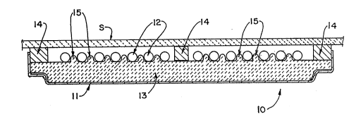
~~ 2~24~rO
Heating Uhit 10 includes pan means 11 ~no~lnted directly
beneath the cooking top s. ~an means 11 contains a heat source
for pro~lding heat to ~he ~ookihg area. The heat sour~e is an
electrical heating means 12 that is insta~led in pan me~ns 11.
Electric heating means 12 supplies an electric~l cu~rent for
heating ~he ~ooking a~ea ~eating means 12 has a low profile and
therefore requires ~ini~um sep~ation with ~ooking top S. ~he
~i~imu~ separation is ac~ieved by using a positive te~perature
~oef~icient materi~l in heating me~ns 12. Positive ~emperature
coerfi~ien~ (P.T.C) is ~ sensor material that ~llows hea~ing
me~ns 12 to be in close proximity with cooking top S creating the
overall low pro~ile. The material provides a more direct and
e~ioient ~pplicatio~ o~ he~t to the underside of cookin~ top S.
~ore specifically, P.T.C. material ~ell~s on wire size of
resistan~e he~ting wire and watts-density loading to maxi~iæe
power usage effioiency. The wire size supplies a spacing wit~in
the ~ea~ing ele~ent that is more effi~ien~ ~y impl~men~ing more
watts/area thah larger wires. This size allows for a more direct
supply o~ heat, takes less space and is more e~fi~ient than the
larger wires. Speci~ically, the.watts-density loading.in~oives a
wire size with respect to the w~tts dissipated, p~oviding;a wire
te~perature transmitted ~y radiation and conduction, that reaches
cri~i~al points of te~pe~ature. These features provide optimum
temperature in the heating ele~en~ for increa~ed o~erall
ef~iciency.
004G~/4~16 UGND
A support means 13 is fitted in the base of pan mear~s 11
for bracing heatin~ means 12. Suppor~ means 13 comprises heat
re1eetive material that enhances powe~ usage efficiency nf the
heati~g element. T~e heat refle~tive material of ~upport means
13 di~ects he~t radiated ~y heating mea~s 12 toward the underside
o~ cooki~g top s
Spacing ~eans 14 separate cooking top S and heatih~
means 12. 5p~cing means 14 m~in~ain a mini~n~n division between
heati~g means 12 and t~e under~ide of cooking top S consistent
with a low profile ~rrangemen~. Lastly, an atta~ihment ~ean~ 15
is used to att~ch heating ~eans lZ tc the upper surface of
support means 13. In one embodiment, as shown in ~ig. 2,
attachment ~eans 15 comprises ridges fo~med in support mea~. 13
to i~terlock with heating means 12.
What ~as been des~ribed is an i~proved heating unît for
use in stove tops. The heating unit hAs an i~proved p~ofile
whiah ~s shallowe~ than conventi~nal heating units so to ~ake up
~s~ space than ~he conventional units. ~his is ac~omplished by
~sing an i~proved P.T.C. he~ting coil which is readily installed
in the ~nit and which allo~s the dista~ce between the coil and
underside of the cooktop to be smalle~ than in t~e con~ent~io~al
heating unitB~ Also, the heating unit has increased e~iciency
because of ~elia~ce upon the wixe size of ~he resistance P.
hQatinq wir~, watts-density loading, and underlayment of
reflective insulation in a pan of the ~nit. The heating ele~ent
can be arran~ed in a variet~ o~ patterns each of which allows
00-6~ t~ 6~6 UCND
8 0
heat energy to be evenly distributed over the cooking surface.
As a result, the heating unit is energy efficient, easy to
manufacture, and has a simplified design which increases its
useful life.
In view of the foregoing, it will be seen that the
several objects of the invention are achieved and other
advantageous results are obtained.
As various changes could be made in the above
constructions without departing from the scope of the invention,
it is intended that all matter contained in the above description
or shown in the accompanying drawings shall be interpreted as
illustrative and not in a limiting sense.
8 --
0046~ 606 I~GND