Note : Les descriptions sont présentées dans la langue officielle dans laquelle elles ont été soumises.
APPLICATION FOR
L~1ITED STATES LETTERS PATENT
Be it known that we, Vladislav L. Goriachev, Alexander N. Bratsev, Valeri N.
Fediukovich, and Philip G. Rutberg, citizens of Russia, each residing in St.
Petersburg, Russia,
and Hugh W. Greene of Somerville, Alabama and Paul E. Chism, Jr. of Decatur,
Alabama,
have invented a new and useful "Method and Apparatus for Water Decontamination
Using
Electrical Discharge" .
BACKGROUND OF THE II~TYENTION
The present invention relates generally to methods and equipment used in the
purification
and decontamination of water, and more particularly to a water purification
method using
electrical discharge within a water stream.
A significant amount of research and development has been undertaken in recent
years
towards environmental clean-up operations, and in particular to the
purification and
decontamination of ground water, waste water, and drinking water. The need for
decontamination of water can vary from the continuous treatment of industrial
waste water to
dealing with one-time contamination of water pools or ponds at a single
location. Accordingly,
methods are needed which are feasible on both a large and small scale.
A variety of techniques have been used in the prior art to destroy or remove
contaminating and toxic materials in water supplies. These include the use of
shock waves
created by ultrasonic vibrations and exposing the water to ultraviolet
radiation. Electricity has
also been employed as a decontamination agent, such as by introducing
positively charged ions
into a water stream to cause coagulation and separation of particles, and by
the passing of
2~~~~
.~
electric current within a fluid chamber whereby the current flow between the
anode and cathode
has a toxic effect on microorganisms nearby.
Chlorination is well known and effective in limiting bacteria and
microorganisms but has
little effect on organic chemicals. Conversely, activated carbon filters can
remove organic
chemicals but such filters are extremely costly and require regular
maintenance.
The use of ozone injection can also be effective. However, to be efficient, an
ozonation
facility must be extremely large. Therefore, its cost and size renders it
unsuitable for use, for
example, to clean up small contaminated ground water and waste water sites.
Hydrogen
peroxide injection systems can also be used but are not preferred because of
the effects of
inorganic contamination and because of the high costs associated with such
systems.
What is needed, then, is a water purification and decontamination method which
can
effectively destroy or remove a variety of organic materials and chemical
toxins at relatively low
cost, which does not require the addition of other chemicals or further
processing of the
contaminated water, and which can be adapted for use in both large and small
scale operations.
Such a method is presently lacking in the prior art.
SUMMARY OF THE INVENTION
One object of the present invention is to provide a method of water
decontamination
which is effective both on bacteria and other microorganisms as well as on
organic chemicals
Yet another object of the present invention is to provide for a method and
apparatus of
water purification which can both be cost effective and efficient whether
being operated on a
large or small scale.
-2-
CA 02126935 2000-O1-31
74697-12
3
A further object of the present invention is to employ a water
purification method which concurrently implements several
different modes of decontamination actions but without adding
complexity to the apparatus itself.
To achieve these and other objectives, the method of
the present invention uses a synergistic combination of
ultraviolet radiation, pulsed mechanical shock waves, and
ionization of the water stream, as decontamination and
purification actions within the water to be treated. The water
to be decontaminated is directed through one or more
decontamination modules arranged in series or parallel. A pair
of electrodes extend transversely across and through a cavity
within the module, defining therein an arc gap or electric
discharge area. Contaminated water is introduced into the
cavity and module through an intake port where it passes
through or proximate to the discharge area. A pulse power unit
delivers a rapid sequence of arc inducing electrical pulses
across the electrodes, thereby producing a series of electric
discharge arcs across the discharge area between the
electrodes. The arcs are of sufficient energy whereby a plasma
inducing arc is sustained through the water across the
electrodes, generating lethal levels of ultraviolet radiation
as well as mechanical shock waves having the capacity of
directly killing microorganisms and weakening others. Further,
molecules of water proximate to the discharge area are broken
down into excited radicals, including hydroxyl ions and free
oxygen, which combine with organic chemicals to eliminate them
from the water stream.
In summary, this invention seeks to provide a method
of water purification comprising the steps of: a) directing the
water to be purified through a decontamination module; and b)
generating by a pulse power unit means an electric discharge
arc within said decontamination module, said pulse power unit
CA 02126935 2000-O1-31
74697-12
3a
means comprising a semiconductor switch, a discharge
capacitor, and a pulse transformer having an input and output;
c) operating said semiconductor switch and said discharge
capacitor at an applied operating voltage and using said
semiconductor switch to discharge said discharge capacitor to
produce and pulse input signal at said input of said pulse
transformer, thereby generating a pulse output signal at said
output of said pulse transformer, the applied operating voltage
being from 375 to 3500 volts, the pulse input signal being from
375 to 3500 volts to give the pulse output signal having a peak
voltage of 10,000 volts to 50,000 volts.
BRIEF DESCRIIrTION OF THE DRAWINGS
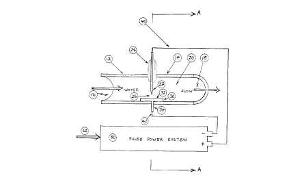
Fig. 1 is a schematic representation of the water decontamination apparatus of
the present
invention with a decontamination module shown in a cut-away view.
Fig. 2 is cutaway plan view of the decontamination module, showing the
geometry of the
electrodes.
Fig. 3 is an end view, looking through the decontamination module of the
apparatus of
the present invention.
Fig. 4 is a schematic diagram of the pulse power unit of the present
invention.
DESCRIPTION OF THE PREFERRED EMBODIMENT
The water decontamination method of the present invention uses three distinct
modes of
purification and decontamination of water, which combine in a synergistic
manner to remove or
destroy organic materials and chemical toxins. The event which initiates each
of these distinct
decontamination modes is a series of pulsed electrical arcs which are produced
within the water
stream. Using a discharge voltage of between 10 kV to 50 kV, with a peak arc
current of 30A,
a plasma effect is created in the arc discharge area. The immediate result is
a localized
temperature of 10,000 to 50,000 degrees K and localized plasma pressures of
between 100 to
1000 MPa. As a first consequence of the discharge, the arc itself generates
high levels of
ultraviolet radiation which is destructive of many living organisms found in
water streams.
Second, the high temperature causes a rapid expansion and then cooling of the
ambient water,
producing a mechanical shock wave within the decontamination unit and
resulting in both
immediate destruction of many bacteria and microorganisms, as well as tire
breaking down of
-4-
2~~~9
protective shells and membranes of others, thereby exposing them to
ultraviolet radiation or
other lethal effects. Thirdly, the electrical discharge breaks down the water
itself into hydrated
electrons, ions, and excited free radicals, including H, OH; HO2, and O+.
These radicals
directly attack the bacteria and viruses and then combine with the organic
chemicals to eliminate
them, similar to the previously mentioned hydrogen peroxide and ozone
injection systems.
Thus, the significant event in the method is the creation of a high energy
electrical arc
within the water. An apparatus which will create such an arc is shown
generally on Fig. 1. The
decontamination and purification effects take place within one or more
decontamination modules
12 through which the ground, waste, or drinking water passes during the
decontamination
process. In a preferred embodiment, module 12 has a generally cylindrically
shaped wall 14
which, in conjunction with water intake port 16 and water discharge port 18,
will define therein
a fluid containing decontamination cavity 20. Preferably, decontamination
module 14 will be
constructed of Lexan~ plastic material, with an inside diameter of
approximately 3 cm.
Mounted transversely on opposing sides of wall 14 are arc inducing electrodes
in the
form of an anode 22 and cathode 30. Anode 22, preferably made of tungsten,
will have a
generally cylindrical shape, approximately 1/8 inch in diameter, terminating
in a point. Anode
22 will be supported as it enters and passes through wall 14 by anode holding
fixture 24, made
of Teflon~ PTFE, and mechanically adapted for easy removal of anode 22 and for
adjusting its
position within cavity 20.
Cathode 30 will have a generally rectangular arcing plate 32 which is
substantially
longitudinally aligned with and proximate to the inner surface of wall 14.
Extending
perpendicularly from the outside or wall contacting surface of arcing plate 32
is a terminal
-5-
~~~~9
portion 34 of cathode 30. A fluid retaining seal (not shown) will be placed
around terminal 34
in a conventional manner to prevent the release of contaminated water from
within module 12.
As seen on Fig.'s 1 and 3, an arc discharge area 26 is defined between the
flat surface
of arcing plate 32 and the pointed end of anode 22. The length of this
discharge area, or
distance between the pointed end of anode 22 and the inward facing surface of
arcing plate 32,
is critical to the proper operation of the decontamination apparatus. The
spacing should be
maximized for optimum flow rate, consistent, however, with the ability to
produce and sustain
a reliable electrical discharge and arc between anode 22 and cathode 30. In a
preferred
embodiment of the invention, the length of discharge area 26 will be
approximately 1.0 cm.
Anode 22 is the only part of the apparatus which requires periodic
replacement.
Therefore, use of a highly durable material in manufacturing the anode is
important. Metals
found acceptable for use in manufacturing anode 22 include tungsten thorium
alloy and
chromemolly alloy.
Cathode 30 can be made of any durable metal which is suitable for long-term
operation,
stainless steel, for example. Discharge plate 32 of cathode 30 should be
approximately 2 cm
by 2cm by 2 cm, with a thickness of 0.2 cm.
To create an arc between anode 22 and cathode 30, anode 22 is connected to
pulse power
unit ~0 by means of positive cable 40. A negative cable 42 is connected also
from terminal
portion 34 of cathode 30 to the negative side of pulse power unit 50.
To achieve the objective of repetitive generation of shock waves within
decontamination
module 12, as a consequence of generation of the arc, means for pulsing the
arc are used.
Looking now at Fig. 4, further detail is provided regarding the design of
pulse power unit 50.
-6-
--. ~~.~~a~
Preferably, pulse power unit 50 will be of the capacitive discharge type,
having a discharge
capacitor 54 with a capacity of forty microfarads and rated at 3,500 volts.
Capacitor 54 is
discharged by means of high power semiconductor switch 56, which is designed
and selected
such that it can discharge the capacitor into output pulse transformer 58 in
one microsecond.
In order to produce a sufficiently high energy electrical arc at discharge
area 26, pulse
transformer 58 must be capable of producing a 40,000-volt, 30-amp pulse at
anode 22, based
on a 1,500-volt, 1,100-amp pulse from discharge capacitor 54. Thus, in the
preferred
embodiment, semiconductor switch 56 must receive a triggering signal from
electronics timing
board 60, which contains circuitry capable of producing between one and sixty
triggering signals
per second. Discharge capacitor 54 is charged to 1,500 volts DC in several
milliseconds by first
stage transformer and rectifier unit 64, which is connected to a conventional
120-volt power line
62.
In one preferred embodiment of the apparatus, timing board 60 will cause the
production
of thirty arcs per second across discharge area 26 at a peak power level of
1.2 megawatts. The
pulse width of the arcing signal is approximately f ve microseconds, providing
an energy level
of approximately 7.0 Joules per pulse with an arc gap or discharge area 26
distance of
approximately of 1.0 centimeters.
The flow rate of water through module 12 can be adjusted to varying levels,
depending
on the energy requirements per volume of water for a preferred amount of
decontamination and
purification effects. In one preferred embodiment, an energy density of 1.0
J/cm3 of water will
provide adequate decontamination, thereby allowing a flow rate of
approximately of twelve liters
per minute through module 12.
.....
It will be apparent to those skilled in the art that the dimensions and volume
of module
12 can be proportionally adjusted in accordance with the type of water to be
purified and the
needed flow rate. Further, to increase decontamination capacity, a plurality
of modules 12 can
be concurrently operated in parallel, from a single contaminated water supply
emptying into a
unitary discharge. Also, to enhance the amount of decontamination effects, a
plurality of
modules 12 can be operated in series, whereby purified water leaving the
discharge port 18 of
the first module 12 will then feed immediately into the intake port 16 of a
second module 12,
and so on.
Based on tests of a prototype system implementing the methods and apparatus
described
herein, purification level of 99.5 %, suitable for drinking water, can be
achieved using an energy
density of 3.5 J/cm3 or 1 KWH/M3. To meet standard environmental requirements,
that is to
achieve a purification level adequate to allow release of the treated water
into the environment,
a power density of .3 KWH/M3 is adequate.
Further testing of a preferred embodiment for the removal of common organic
chemical
contaminants showed that reduction of such contaminants occurs at an arc
energy level of
between 10 - 30 J/cm3 occurs, whereby a 90 to 95 % reduction in contaminants
was obtained for
pesticides from an initial concentration of .1 grams per liter, for
hydrocarbons from .1 to 40
grams per liter, and for oil products from between .2 and 20 grams per liter.
Thus, although there have been described particular embodiments of the present
invention
of a new and useful method and apparatus for water decontamination using
electrical discharge,
it is not intended that such references be construed as limitations upon the
scope of this invention
except as set forth in the following claims. Further, although there have been
described certain
_g_
~i~~~~
dimensions and operational parameters used in the preferred embodiment, it is
not intended that
such dimensions be construed as limitations upon the scope of this invention
except as set forth
in the following claims.
-9-