Sélection de la langue

Search

Sommaire du brevet 2127235 

Énoncé de désistement de responsabilité concernant l'information provenant de tiers

Une partie des informations de ce site Web a été fournie par des sources externes. Le gouvernement du Canada n'assume aucune responsabilité concernant la précision, l'actualité ou la fiabilité des informations fournies par les sources externes. Les utilisateurs qui désirent employer cette information devraient consulter directement la source des informations. Le contenu fourni par les sources externes n'est pas assujetti aux exigences sur les langues officielles, la protection des renseignements personnels et l'accessibilité.

Disponibilité de l'Abrégé et des Revendications

L'apparition de différences dans le texte et l'image des Revendications et de l'Abrégé dépend du moment auquel le document est publié. Les textes des Revendications et de l'Abrégé sont affichés :

  • lorsque la demande peut être examinée par le public;
  • lorsque le brevet est émis (délivrance).
(12) Demande de brevet: (11) CA 2127235
(54) Titre français: MACHINE DE FORAGE HYDRAULIQUE
(54) Titre anglais: FLUID DRIVEN DOWN-THE-HOLE DRILLING MACHINE
Statut: Morte
Données bibliographiques
(51) Classification internationale des brevets (CIB):
  • E21B 4/20 (2006.01)
  • B25D 17/06 (2006.01)
  • E21B 4/14 (2006.01)
  • E21B 31/107 (2006.01)
(72) Inventeurs :
  • EKWALL, BERNDT (Suède)
  • PETERSON, MARTIN (Suède)
(73) Titulaires :
  • ATLAS COPCO ROCKTECH AB (Suède)
(71) Demandeurs :
(74) Agent: FETHERSTONHAUGH & CO.
(74) Co-agent:
(45) Délivré:
(22) Date de dépôt: 1994-06-30
(41) Mise à la disponibilité du public: 1995-01-13
Requête d'examen: 2001-06-06
Licence disponible: S.O.
(25) Langue des documents déposés: Anglais

Traité de coopération en matière de brevets (PCT): Non

(30) Données de priorité de la demande:
Numéro de la demande Pays / territoire Date
9302391-9 Suède 1993-07-12

Abrégés

Abrégé anglais


Abstract:

Fluid driven down-the-hole drilling machine. The hammer piston (2) of the
down-the-hole drilling machine is adjacent to its front end provided with a cylindrical
part (6). The drill bit (3) is provided with a first impact surface (41) which receives
impacts during drilling, a second impact surface (42) and an annular section (7) which
surrounds the cylindrical part (6) between the impact surfaces. The second impact
surface (42) receives the impact energy of the hammer piston at reversed feeding of
the housing (1) of the down-the-hole drilling machine for freeing the drill bit when it
has become stuck.

Revendications

Note : Les revendications sont présentées dans la langue officielle dans laquelle elles ont été soumises.


Claims:

1. Fluid driven down-the-hole drilling machine comprising a housing (1), ahammer piston (2) movable to-and-fro in the housing and intended for impacting adrill bit (3) arranged in the housing and a valve (4) for alternately connecting at least
one (5) of two driving surfaces (5,16) on the hammer piston to a pressure source (9)
or low pressure, c h a r a c t e r i z e d in that the hammer piston (2) comprises a
cylindrical part (6), that the drill bit (3) comprises a first impact surface (41), a second
impact surface (42) and an annular section (7) arranged between said impact surfaces
and surrounding a major part of said cylindrical part on the hammer piston (2),
whereby said first impact surface (41) is impacted during drilling and said second
impact surface (42) transfers impact energy from the hammer piston (2) to the drill bit
(3) when said housing (1) is fed in a direction away from the drill bit (3).

2. Down-the-hole drilling machine according to claim 1,
c h a r a c t e r i z e d in that the hammer piston adjacent to said cylindrical part (6)
is provided with a part (43) with reduced diameter and the drill bit (3) between said
impact surfaces (41,42) is provided with a first slot (44), through which said
cylindrical part (6) can be moved into the drill bit (3) from the side.

3. Down-the-hole drilling machine according to claim 2,
c h a r a c t e r i z e d in that said part (43) with reduced diameter on the hammer
piston (2) comprises two diametrically oppositely arranged plane surfaces (45) and the
drill bit comprises a second slot (46), whereby the part (43) with reduced diameter on
the hammer piston (2) at the plane surfaces (45) can pass said second slot (46) at the
same time as said cylindrical part (6) is moved into the drill bit (3) through said first
slot (44).

Description

Note : Les descriptions sont présentées dans la langue officielle dans laquelle elles ont été soumises.


'~ 93003.utl ~ "~,


Fluid driven down-the-hole drillin machine

The present invention relates to a fluid driven down-the-hole drilling machine, i.e. a
drilling machine driven by liquid or gas. More specifically the invention relates to a
down-the-hole drilling machine provided with a backhammer for freeing a drill bit
which has become stuck.

In a prior art backhammer for down-the-hole drilling machines, see DE 3802391, aseparate backhammer unit is used which when needed is connected to the drill string
in order to free the drill bit by means of impacts in a direction away from the drill bit. ~,
This device is very time-consuming to use.

The present invention, which is defined in the subsequent claims, aims at achieving a
fluid driven down-the-hole drilling machine where the drill bit is easily freed when
stuck through reverse feed of the down-the-hole drilling machin~.
`~:
An embodiment of the invention is described below with reference to the
accompanying drawing in which fig lA shows the front part of a fluid driven
down-the-hole drilling machine according to the invention. Fig lB shows the rear part
of the down-the-hole drilling machine. Fig 2 shows a section according to 2-2 in fig ,l' "
lA. Fig 3 shows a section according to 3-3 in fig lA.,Fig 4 shows a section according
to 4-4 in fig lA.
'~
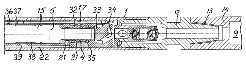
The, fluid driven down-the-hole drilling machine shown in the drawing comprises a
housing 1 in the front end of which a drill bit 3 is arranged. The drill bit is connected
to the housing 1 by means of a splined coupling 11. The drill bit comprises a shaft
part 3 and a head part 51 provided with not shown hard metal bottons. The shaft part
3 and the head part 51 are connected with each other by means of a ~read coupling
52. The housing 1 is at its rear end provided with an end piece 12 which by means of ' '~
a thread coupling 13 is connected to a tube string 14. The drill bit 3 is during drilling
turned through rotation of the tube string 14, end pie~e 12 and housing 1 via the
splined coupling 11. Fluid for the driving of the down-the-hole drilling machine is
supplied firom a not shown pump via the channel 9 in the tube string. The channel 9


... ":,;,,-,~' ","~ ~ '

93003 u~
r ~

thus functions as a pressure source. A hammer piston 2 is movable to-and-fro in the
housing 1. The hammer piston is provided with a piston head 15 with a first driving
surface 5. The hammer piston 2 is guided in the housing 1 by the piston head 15 and
a guide 1~. The hammer piston 2 iS provided with a second driving surface 16 which
is continuously pressurized via channel 17 during drilling. The to-and-fro movement
of the hammer piston is controlled by the valve 4 which alternately connects thedriving surface 5 to the pressure source 9 or to a low pressure via channels 21, 22,
slot 23, groove 24 and channel 25 to the environment for flushing of the borehole.
The charnber 31 around the valve 4 is continuously pressurized via channels 17 and
32. This pressure strives at moving the valve 4 to the right in the drawing for
cooperation with a valve seat 33, through which the connection between the pressure
source 9 and the first driving surface 5 via channel 34 is interrupted. Through this the
connection via channels 21 and 22 to low pressure is opened. The movement
to-and-fro of valve 4 is controlled by the pressure in chamber 35 which surrounds
valve 4. Pressurization of chamber 35 moves valve 4 to the left in the drawing since
the pressurized surface in chamber 35 is larger than the pressurized surface in
chamber 31. The charnber 35 is via not shown channels connected to holes in the
cylinder wall surrounding the hammer piston 2. These holes, which lie in anothersection than the one shown, are marked with the reference numerals 36 and 37. In the
shown position of the hammer piston 2 charnber 35 is connected to low pressure via
channel 37, the turndown 38 on the hammer piston 2 and the channels 39 and 22.
When the hammer piston is in its rearward position chamber 35 is pressurized via the
channel 17 and the channel 36.

The harnmer piston 2 is at its front end formed with a cylindrical part 6. Adjacent to
the cylindrical part the hammer piston is formed with a part 43 with reduced diameter. ;
The part with reduced diameter is provided with two diametrically oppositely arranged
plane surfaces 45. The shaft part 3 of the drill bit is rearwardly forrned with an
annular section 7 which surrounds the major part of the cylindrical part 6 of the
hammer piston. The drill bit 3 comprises a first impact surface 41 against which the -
hammer piston 2 impacts during drilling. The drill bit 3 furthermore comprises asecond impact surface 42 against which the cylindrical part 6 can impact whein the
housing 1 is fed in a direction away from the drill bit 3. The annular section 7

93003.utl 2 ~ ~ 7 ?~


comprises a first slot 44 the width of which allows the cylindrical part 6 on the drill
bit 2 to be moved into the drill bit 3 from the side when the front tube 61 of the
housing 1 has been loosened at the thread coupling 62. The annular section 7
furthermore comprises a second slot 46 the width of which corresponds to the
distance between the two plane surfaces 45 on the part 43 with reduced diameter so
that this part can pass the second slot 46 at the same time as the cylindrical part 6 is ~ '
moved in through the first slot 44. Since the part 43 with reduced diameter has been
made with two plane surfaces 45 the second slot 46 can be made narrower. This
means that the surface of the second impact surface 42 can be made larger so that
stress is reduced.

The drill bit 3 is mounted in the following way. The shaft part 3 and the head part 51
are separated from each other and the tube 61 of the housing 1 is screwed off. In this ~;
state the hammer piston 2 protrudes from the housing 1. The shaft part 3 is aligned so
that the cylindrical part 6 on the hammer piston 2 can be moved into the shaft part 3
through the first slot 44 at the same time as the two plane surfaces 45 on the hammer
piston 2 are held in position for passage through the second slot 46. After this the
shaft part 3 is moved on to the hamrner piston 2 from the side and is pushed to the ~ ~-
right in the drawing to the position shown in the drawing. After this the tube 61 is
pushed on to the shaft part 3 so that the splined coupling 11 is created, after which ,
the thread coupling 62 is fastened. After this the head,part 51 is screwed on to the
shaft part 3.

The shown fluid driven down-the-hole drilling machine works in the following way.
At drilling the hammer piston is driven to-and-fro as described above for impacting
the drill bit 3. If the drill bit tends to become stuck the feed is reversed, i.e. the tube
string 14 is driven to the right in fig lB. Through this the cylindrical part 6 on the
hammer piston 2 will impact the second impact surface 42 during the movement
to-and-fro of the hammer piston 2, through which ~e drill bit will be impacted to
become free. This operation is automatically obtained at reverse feed.

Dessin représentatif
Une figure unique qui représente un dessin illustrant l'invention.
États administratifs

Pour une meilleure compréhension de l'état de la demande ou brevet qui figure sur cette page, la rubrique Mise en garde , et les descriptions de Brevet , États administratifs , Taxes périodiques et Historique des paiements devraient être consultées.

États administratifs

Titre Date
Date de délivrance prévu Non disponible
(22) Dépôt 1994-06-30
(41) Mise à la disponibilité du public 1995-01-13
Requête d'examen 2001-06-06
Demande morte 2005-11-17

Historique d'abandonnement

Date d'abandonnement Raison Reinstatement Date
2004-11-17 R30(2) - Absence de réponse
2005-06-30 Taxe périodique sur la demande impayée

Historique des paiements

Type de taxes Anniversaire Échéance Montant payé Date payée
Le dépôt d'une demande de brevet 0,00 $ 1994-06-30
Enregistrement de documents 0,00 $ 1994-12-16
Taxe de maintien en état - Demande - nouvelle loi 2 1996-07-01 100,00 $ 1996-05-24
Taxe de maintien en état - Demande - nouvelle loi 3 1997-06-30 100,00 $ 1997-05-23
Taxe de maintien en état - Demande - nouvelle loi 4 1998-06-30 100,00 $ 1998-06-10
Taxe de maintien en état - Demande - nouvelle loi 5 1999-06-30 150,00 $ 1999-05-17
Taxe de maintien en état - Demande - nouvelle loi 6 2000-06-30 150,00 $ 2000-05-17
Taxe de maintien en état - Demande - nouvelle loi 7 2001-07-02 150,00 $ 2001-05-03
Requête d'examen 400,00 $ 2001-06-06
Taxe de maintien en état - Demande - nouvelle loi 8 2002-07-01 150,00 $ 2002-05-07
Taxe de maintien en état - Demande - nouvelle loi 9 2003-06-30 150,00 $ 2003-05-05
Taxe de maintien en état - Demande - nouvelle loi 10 2004-06-30 250,00 $ 2004-05-04
Titulaires au dossier

Les titulaires actuels et antérieures au dossier sont affichés en ordre alphabétique.

Titulaires actuels au dossier
ATLAS COPCO ROCKTECH AB
Titulaires antérieures au dossier
EKWALL, BERNDT
PETERSON, MARTIN
Les propriétaires antérieurs qui ne figurent pas dans la liste des « Propriétaires au dossier » apparaîtront dans d'autres documents au dossier.
Documents

Pour visionner les fichiers sélectionnés, entrer le code reCAPTCHA :


Pour visualiser une image, cliquer sur un lien dans la colonne description du document. Pour télécharger l'image (les images), cliquer l'une ou plusieurs cases à cocher dans la première colonne et ensuite cliquer sur le bouton "Télécharger sélection en format PDF (archive Zip)" ou le bouton "Télécharger sélection (en un fichier PDF fusionné)".

Liste des documents de brevet publiés et non publiés sur la BDBC .

Si vous avez des difficultés à accéder au contenu, veuillez communiquer avec le Centre de services à la clientèle au 1-866-997-1936, ou envoyer un courriel au Centre de service à la clientèle de l'OPIC.


Description du
Document 
Date
(yyyy-mm-dd) 
Nombre de pages   Taille de l'image (Ko) 
Dessins représentatifs 1998-03-02 1 43
Dessins 1995-06-08 1 96
Dessins représentatifs 2003-06-27 1 17
Page couverture 1995-06-08 1 64
Abrégé 1995-06-08 1 39
Revendications 1995-06-08 1 75
Description 1995-06-08 3 229
Cession 1994-06-30 6 238
Poursuite-Amendment 2001-06-06 1 48
Poursuite-Amendment 2004-05-17 3 114
Taxes 1997-05-23 1 75
Taxes 1996-05-24 1 64