Sélection de la langue

Search

Sommaire du brevet 2129814 

Énoncé de désistement de responsabilité concernant l'information provenant de tiers

Une partie des informations de ce site Web a été fournie par des sources externes. Le gouvernement du Canada n'assume aucune responsabilité concernant la précision, l'actualité ou la fiabilité des informations fournies par les sources externes. Les utilisateurs qui désirent employer cette information devraient consulter directement la source des informations. Le contenu fourni par les sources externes n'est pas assujetti aux exigences sur les langues officielles, la protection des renseignements personnels et l'accessibilité.

Disponibilité de l'Abrégé et des Revendications

L'apparition de différences dans le texte et l'image des Revendications et de l'Abrégé dépend du moment auquel le document est publié. Les textes des Revendications et de l'Abrégé sont affichés :

  • lorsque la demande peut être examinée par le public;
  • lorsque le brevet est émis (délivrance).
(12) Brevet: (11) CA 2129814
(54) Titre français: SYSTEME D'AERATION A L'EPREUVE DE LA PLUIE
(54) Titre anglais: ROOF VENT RAIN DEFLECTOR
Statut: Durée expirée - au-delà du délai suivant l'octroi
Données bibliographiques
(51) Classification internationale des brevets (CIB):
  • F24F 7/02 (2006.01)
  • B60H 1/26 (2006.01)
  • F24F 13/10 (2006.01)
(72) Inventeurs :
  • PINDER, ROBERT CLAYTON (Canada)
(73) Titulaires :
  • MILDRED GRACE PINDER
  • ELIZABETH CHERYL ZVANIGA
  • BRYAN NORMAN PINDER
(71) Demandeurs :
  • MILDRED GRACE PINDER (Canada)
  • ELIZABETH CHERYL ZVANIGA (Canada)
  • BRYAN NORMAN PINDER (Canada)
(74) Agent: AVENTUM IP LAW LLP
(74) Co-agent:
(45) Délivré: 1997-03-04
(22) Date de dépôt: 1994-08-09
(41) Mise à la disponibilité du public: 1996-02-10
Requête d'examen: 1994-08-09
Licence disponible: S.O.
Cédé au domaine public: S.O.
(25) Langue des documents déposés: Anglais

Traité de coopération en matière de brevets (PCT): Non

(30) Données de priorité de la demande: S.O.

Abrégés

Abrégé français

Un déflecteur de pluie pour un évent de toit de véhicule se compose d'une paire de panneaux identiques dont un est fixé sur le capuchon de l'évent de toit et se déplace avec celui-ci, et est articulé au deuxième panneau dont l'extrémité éloignée de la charnière est connectée de manière à glisser le long de rails sur le toit du véhicule. Chaque panneau est nettement plus grand que le bouchon d'évent, de manière à s'étendre au-delà des bords de l'évent et à empêcher la pluie de pénétrer dans l'évent tout en permettant la ventilation par l'évent.


Abrégé anglais

A rain deflector for a vehicle roof vent consists of a pair of like panels one of which is fastened to the cap of the roof vent and moves therewith, and is hinged to the second panel which has the end remote from the hinge connected to slide along tracks on the vehicle roof. Each panel is substantially larger than the vent cap, to extend beyond the edges of the vent and prevents rain from entering the vent while permitting ventilationof air through the vent.

Revendications

Note : Les revendications sont présentées dans la langue officielle dans laquelle elles ont été soumises.


- 6 -
CLAIMS
1. A roof vent rain deflector adapted to cooperate with a standard
hinged cap roof to prevent rain from entering the vent when said
cap is raised, said deflector comprising;
a first panel adapted to be attached to and overlie said cap
and extend beyond the edges of said cap for a distance
approximately half the width of said cap,
a second panel of substantially the same size as said first
panel hinged to said first panel at the end of said first panel
remote from the hinged end of said roof cap,
track means adapted to be fastened to the roof of a vehicle
equipped with said roof vent, and positioned to provide a sliding
connection to the unhinged end of said second panel,
and means connecting said second panel in sliding relation to
said track means , whereby when said cap is opened, said first
panel is moved with said cap, and the edge of said second panel
which is hinged to said first panel moves upwardly towards said
roof cap, and the unhinged edge of said second panel moves along
said track means, said two panels forming a pair of triangular
openings permitting flow of air from said vent while preventing
rain from entering therein.
2. A rain deflector as claimed in claim 1, wherein said first and
second panels and said hinge are formed froma single sheet of
thermoplastic material
3. A rain deflector as claimed in claim 1, wherein said tracks
are formed of metal, and are provided with a longitudinally
extending slot in each track, and a sliding axle assembly is

- 7 -
connected to each side of said second panel and slides in said slot
in said track.
4. A rain deflector as claimed in claim 1,2,or 3 including splash
matting adapted to be positioned adjacent said roof vent to
prevent rain from bouncing on said roof and into said vent.

Description

Note : Les descriptions sont présentées dans la langue officielle dans laquelle elles ont été soumises.

ROOF VENT RAIN DFFLFCTOR 2 ~. 2 9 ~14
FIFLD OF ~ NVh..llON
The present invention relates to a device which, when
installed over a standard vehicle ventilating hatch, allows a full
flow of warm air out of the vehicle through the hatch, and also
keeps rain from entering the vehicle through the hatch.
The standard roof vent used by most recreation vehicles
in North America has a fourteen inch square opening through the
roof, over which an adjustable hatch vent unit is installed. This
unit has a crank-up mechanism attached to a hinged cap, which when
closed, keeps out the rain, but when raised to full height rotates
upward at approximately a fifty to sixty degree angle to the
horizontal, allowing full ventilation. Unfortunately, when open,
the vent cannot prevent rain from entering the vehicle that it is
installed upon.
BAC~OUND OF 1~ lNv~ ON
There are known units for moving vehicles, buses and cars
using openings in the roof and covered by a fixed lid mounted over
openings which vent out the back of the lid. Another type is a
dome mounted permanently over the roof vent with a small screened
and louvered area on one vertical side. Reference is made to
United States Patents 4,592,269 dated June 30, 1986 to Lamparter
and 1,539,534 dated May 1925 to Ansell, which show examples of such
prior art devices. Although these units keep rain out of a
vehicle, the volume of air exhausted is very small when the vehicle
~r

2.t..29~i~
is stationary. These units need forward motion to provide adequate
ventilation.
There has been a need for rain protection plus full
ventilation for as long as these types of roof vents have been
used. Also, a survey of registered recreation vehicles shows over
twenty-six million units in North America. Accordingly, there is
a well defined demand for the device of the present invention.
BRI8F D8SCRIPTION OF 1~ DRAWINGS:
In the accompanying drawings,
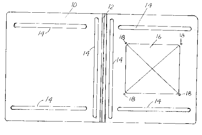
Figure 1 is a top view of the roof vent rain deflector of the
invent ion;
Figure 2 is an end view of the deflector shown in Figure 1 showing
two support legs which are used to support the sliding end section
of the deflector;
Figure 3 is a side view of the deflector shown in Figure 1 showing
a rear support leg, hinged centre area and a domed section shaped
to fit over and embrace a vent roof cap.
Figure 4 is a side view of the slide track showing the slotted area
and mounting fasteners to mount the deflector to the roof of a
vehicle;
Figure 5 is an exploded view of a support leg, the end of a slide
track and sliding axle assembly;
Figure 6 is a top view of the slide track of Figure 5 with the
sliding axle assembly engaged in the track;
Figure 7 is a side view of the deflector of Figure 1 installed on
a vehicle roof;

2~ 29~3i4
Figure 8 is a top view of the device installed on a roof vent
hatch, in the closed position, and
Figure 9 is a side view of a the well known roof vent used on most
recreation vehicles partially open, and showing how easily rain may
enter the vent. This illustrates type of unit that the deflector
is intended to protect.
D~TAIL~D D~SCRIPTION OF 1~ INVENTION
Referring to Figure 1 there is shown a plastic one-piece
lid 10, having a flexible integral hinge 12, and reinforcing ribs
14. One end of the lid 10 has a domed section 16 and is provided
with four mounting holes 18 for attachment to the cap of a roof
vent.
Figure 2 is an end elevation of the lid 10 of Figure 1
showing support legs 20 extending below the lid 10. In Figure 3
the lid 10 is shown in side view, clearly showing the relationship
of the the domed section 16, the flexible hinge 12 and the support
legs 20.
Figures 4, 5, and 6 illustrate a slide track 22, fasteners 24 used
to mount the slide track 22 to the roof of the vehicle, and the
sliding axle assembly 26 used to connect the support legs 20
(Figure 2) to the the slide tracks 22 of the device. The sliding
axle assembly 26 consists of a bolt 38, a sleeve 40, nuts 42 and
washers 44 It will be appreciated by those skilled in the art
that two slide tracks 22 and two sliding axle assemblies 26 are
required for each lid 10, the tracks 22 being mirror images of

2~ 29~i4
each other and mounted on the vehicle roof on opposite sides of the
roof vent frame, as explained hereinafter.
Figure 7, which is a side view of the deflector mounted
on the roof of a vehicle 36, with the roof vent hatch assembly in
a partly open position, illustrates the operation of the deflector
of the present invention. In the open position, the lid 10 is
urged upward by the roof vent cap 34 and folds along flexible hinge
12 with domed section 16 nesting with the vent cap 34. Sliding
axle assemblies 26 slide along slide tracks 22, permitting full
flow of exhaust air through the vent opening, while covering the
vent opening to prevent rain from entering the vent. Vent frame 30
defines the area of the opening over which the cap spans when the
vent is in the closed position. Arm 32 is a component of the roof
vent mechanism, which controls the position of the cap 34, and does
not form part of the device of the present invention. A splash
arresting mat 28 is positioned on either side of the roof vent
frame 30 to prevent splashing of rain drops from the roof into the
vent opening. As shown, tracks 22 are mounted parallel to the
sides of the roof vent frame, but displaced to the end of the frame
which would be the down wind end when the vehicle is in motion.
Figure 8 is a plan view of the deflector of the present invention
in closed position, and mounted on the roof of a vehicle over the
roof vent. The tracks 22 are fastened directly to the vehicle roof
36 with the sliding axle assemblies 26 engaged in the slots of the
tracks 22 and with the domed section 16 of the deflector secured to
the vent cap by fastenings (not shown) passing through mounting

2l2~14
holes 18 and connected to the vent cap. The splash arresting mat
sections 28 are partially visible extending beyond the edges of the
deflector.
Figure 9 illustrates the prior art situation where no
protection is provided to prevent rain from enteringthe roof vent,
highlighting the risk of such a vent admitting rain.
Thus the rain deflector of the present invention serves
to keep rain from entering an open roof vent while permitting full
ventilation through the vent.

Dessin représentatif
Une figure unique qui représente un dessin illustrant l'invention.
États administratifs

2024-08-01 : Dans le cadre de la transition vers les Brevets de nouvelle génération (BNG), la base de données sur les brevets canadiens (BDBC) contient désormais un Historique d'événement plus détaillé, qui reproduit le Journal des événements de notre nouvelle solution interne.

Veuillez noter que les événements débutant par « Inactive : » se réfèrent à des événements qui ne sont plus utilisés dans notre nouvelle solution interne.

Pour une meilleure compréhension de l'état de la demande ou brevet qui figure sur cette page, la rubrique Mise en garde , et les descriptions de Brevet , Historique d'événement , Taxes périodiques et Historique des paiements devraient être consultées.

Historique d'événement

Description Date
Inactive : Demande ad hoc documentée 2018-06-06
Exigences relatives à la révocation de la nomination d'un agent - jugée conforme 2018-05-18
Exigences relatives à la nomination d'un agent - jugée conforme 2018-05-18
Inactive : Périmé (brevet - nouvelle loi) 2014-08-09
Lettre envoyée 2010-05-11
Inactive : Transfert individuel 2010-04-23
Lettre envoyée 2008-08-14
Inactive : Transfert individuel 2008-08-05
Inactive : Regroupement d'agents 2003-12-09
Accordé par délivrance 1997-03-04
Déclaration du statut de petite entité jugée conforme 1996-03-19
Demande publiée (accessible au public) 1996-02-10
Toutes les exigences pour l'examen - jugée conforme 1994-08-09
Exigences pour une requête d'examen - jugée conforme 1994-08-09

Historique d'abandonnement

Il n'y a pas d'historique d'abandonnement

Historique des taxes

Type de taxes Anniversaire Échéance Date payée
TM (brevet, 4e anniv.) - petite 1998-08-10 1998-08-07
TM (brevet, 5e anniv.) - petite 1999-08-09 1999-08-06
TM (brevet, 6e anniv.) - petite 2000-08-09 2000-07-18
TM (brevet, 7e anniv.) - petite 2001-08-09 2001-08-01
TM (brevet, 8e anniv.) - petite 2002-08-09 2002-08-07
TM (brevet, 9e anniv.) - petite 2003-08-11 2003-07-25
TM (brevet, 10e anniv.) - petite 2004-08-09 2004-07-27
TM (brevet, 11e anniv.) - petite 2005-08-09 2005-07-25
TM (brevet, 12e anniv.) - petite 2006-08-09 2006-07-12
TM (brevet, 13e anniv.) - petite 2007-08-09 2007-06-22
TM (brevet, 14e anniv.) - petite 2008-08-11 2008-06-19
Enregistrement d'un document 2008-08-05
TM (brevet, 15e anniv.) - petite 2009-08-10 2009-07-29
Enregistrement d'un document 2010-04-23
TM (brevet, 16e anniv.) - petite 2010-08-09 2010-06-30
TM (brevet, 17e anniv.) - petite 2011-08-09 2011-08-05
TM (brevet, 18e anniv.) - petite 2012-08-09 2012-08-08
TM (brevet, 19e anniv.) - petite 2013-08-09 2013-08-07
Titulaires au dossier

Les titulaires actuels et antérieures au dossier sont affichés en ordre alphabétique.

Titulaires actuels au dossier
MILDRED GRACE PINDER
ELIZABETH CHERYL ZVANIGA
BRYAN NORMAN PINDER
Titulaires antérieures au dossier
ROBERT CLAYTON PINDER
Les propriétaires antérieurs qui ne figurent pas dans la liste des « Propriétaires au dossier » apparaîtront dans d'autres documents au dossier.
Documents

Pour visionner les fichiers sélectionnés, entrer le code reCAPTCHA :


Pour visualiser une image, cliquer sur un lien dans la colonne description du document. Pour télécharger l'image (les images), cliquer l'une ou plusieurs cases à cocher dans la première colonne et ensuite cliquer sur le bouton "Télécharger sélection en format PDF (archive Zip)" ou le bouton "Télécharger sélection (en un fichier PDF fusionné)".

Liste des documents de brevet publiés et non publiés sur la BDBC .

Si vous avez des difficultés à accéder au contenu, veuillez communiquer avec le Centre de services à la clientèle au 1-866-997-1936, ou envoyer un courriel au Centre de service à la clientèle de l'OPIC.


Description du
Document 
Date
(aaaa-mm-jj) 
Nombre de pages   Taille de l'image (Ko) 
Page couverture 1996-03-29 1 14
Description 1996-02-10 2 68
Abrégé 1996-02-10 1 42
Revendications 1996-02-10 1 30
Dessins 1996-02-10 4 55
Dessins 1996-04-07 4 55
Page couverture 1996-04-07 1 14
Revendications 1996-04-07 1 30
Abrégé 1996-04-07 1 42
Description 1996-04-07 2 68
Page couverture 1997-02-25 1 13
Abrégé 1997-02-25 1 15
Description 1997-02-25 5 169
Dessins 1997-02-25 5 89
Revendications 1997-02-25 2 49
Dessin représentatif 1999-06-22 1 15
Courtoisie - Certificat d'enregistrement (document(s) connexe(s)) 2008-08-14 1 104
Courtoisie - Certificat d'enregistrement (document(s) connexe(s)) 2010-05-11 1 101
Taxes 1998-08-07 2 65
Taxes 2001-08-01 1 35
Taxes 2000-07-18 1 30
Taxes 1999-08-06 1 36
Taxes 2011-08-05 1 200
Taxes 1996-08-12 2 72
Taxes 1995-08-31 2 72
Correspondance de la poursuite 1996-03-19 2 48
Correspondance reliée au PCT 1996-11-28 1 30
Correspondance reliée au PCT 1996-12-13 1 32
Correspondance reliée au PCT 1996-12-17 1 92
Demande de l'examinateur 1995-09-19 2 90
Courtoisie - Lettre du bureau 1997-01-21 1 16
Courtoisie - Lettre du bureau 1996-05-06 1 20