Note : Les descriptions sont présentées dans la langue officielle dans laquelle elles ont été soumises.
!;'.'.':' " ' ' ' ' . ~ ' ' ' ' ' .
03
. ~ .
P~ A~ AND PEDA~-LE~GTH C~NTROLLE~ ~O:R AUTOMOBILE
Backqround of the Invention
The present invention relates to a pedal and pedal-length
controller for an automobile, and more particularly, to a ~
pedal and pedal-length controller for an automobil~ whose ~ -
.............................................................................. .... ............ ...
structure is improved to control the length of a pedal in
accordance with the length of a driver's legs.
Automobiles are ordinarily equipped with foot-operated
pedals such as an accelerator, clutch and brake;. Referring to
Fig.1 showing the general relationship between a conventional
pedal and a car seat, a pedal 1 having a predetermined length
is hinged to a plate 2. Here, in order to facilitate pedal -~
operation when seated on a driver's seat 3 having a seat back ~;
4, the operator (driver) adjusts the seat forward or backward ~-
according to the driver's height, or more specifically, ~ ~ -
according to the length of the driver's ~egs. ;- -~-
However, when the very short-legged driver drives with
driver's seat 3 pulled completely forward, certain
inconveniences and/or problems follow. First, when the driver
uses a side mirror or rear-view mirror, his or her head is in ~ ;
an awkwardly contorted position, making it difficult to
simultaneously observe forward and side areas, which is
unsafe. Second, since the driver is thus positioned
uncomfortably close to the steering wheel, proper wheel
operation is difficult. Third, when the driver operates the
pedal, the leg's ariculate angle is almost rectangular so that
.. ~".~
,,,, ~,~
2~3~)379 ;~ ';'9
, ,
eas-y opera~ion o~ th2 automobile is hindered.
Meanwhile, if the driver undertakes to drive with
driver's seat 3 pushed too far back for the length of his or
her legs, the driver operates the pedals with his or her legs `~
overly extended, which quickens leg fatigue during long trips.
In an attempt to remedy this situation, drivers often fix
driver's seat 3 at a position forward enough so that the pedal
is easy to operate, and then leans the seat back 4 in order to -
increase the distance between his or her upper body and the
~ - - -;
steering wheel. In such an event, the driver is in a near
prone position which is not conducive for safe;driving, nor is
it comfortable since it tends to create pains in the neck,
shoulder or back.
,':
Summary of the Invention
Therefore, in order to overcome such problems, it is an
object of the present invention to provide a pedal and pedal- i~
length controller for an automobile whose structure is
improved so that a driver, while maintaining a sufficient
distance from the steering wheel and dashboard, can drive in
the most comfortable and safe position.
To accomplish the object of the present invention, there
is provided a pedal for an automobile comprising a pedal lever
member rotatably supported to the frame of the automobile, and
a pedal plate installed to the pedal lever member, the pedal
further comprising a controller for controlling the radius of
gyration of the pedal plate. ~ i
To accomplish the object of the present invention, there
','':' ~ .
~0379 : ~
. . . . .
is provided a pedal~lencjLh cGntrollar for an automobile : ::
comprising: a pedal lever member rotatably supported to the :
frame of the automobile; a pedal plate installed to the pedal
lever member; an auxiliary pedal member connected to the pedal
plate; and connection means for connecting the auxiliary pedal ~ ~
member to the pedal plate. ~; .
,.,,~
Brief.Descri~tion of the Drawinqs
The above object and advantages of the present invention
will become more apparent by describing in detail a preferred
embodiment thereof with reference to the attached drawings in
which~
Fig.l is a schematic of a conventional pedal for an
automobile and its relative position with respect to a car -.
: seat;
Fig. 2 is a schematic exploded ~erspective view of a pedal -.
; for an~automobile of the present invention,
Figs.3 and 4 are exploded perspective views of other
embodiments of the pedal for an automobile of the present
,
: ~ :invention;
Fig.5 is an exploded perspective view of another
embodiment of the pedal for an automobile of the present : ~:
invention; :~ .. ;
Fig.6 is an exploded perspective view of one embodiment
of a pedal-length controller of an automobile of the present
-~ ,~: ....~.
invention;
Fig.7 i5 a coupled perspective view of Fig.6; .
~,~ ~. .,,; .
~ Figs.8, 9 and 10 are perspective views of other ;~. `.
~ , ., ~ .
''~
~` :~
2~130379 ~
-- , ,
Pmbodiments of the p~dal-length controller for an autGmobile
of the present invention; - ;~-
Fig.11 is a perspective view of another embodiment of the ~ ~
pedal plate of the present invention, and ;
Fig.12 is an exploded perspective view of still another ;~
embodiment of the pedal-length controller for an automobile of- `
the present invention.
_tailed Description of the Invention
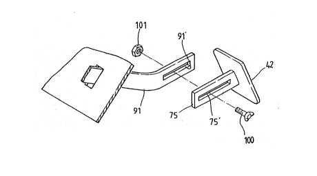
Fig.2 shows a pedal for an automobile of the present
invention having a controller for controlling the radius of
gyration of a pedal plate 42. The controller is constructed so -
that a slot 91' is formed on a pedal lever member 91 rotatably `~ ~ -
supported to the frame of an automobile, and an extension
lever 75, in which a slot 75' is formed corresponding to slot
91' of pedal Iever member 91, is formed on pedal plate 42.
; Pedal lever member 91 and extension lever 75 are placed so as
to oppose each other at a predetermined position and are fixed
~; together with a fastening member via the slots. Here, the
~ fastening member is comprised of a bolt 100 and a nut 101 ~ ;
;~ 20 coupled to slots 91' and 75', as shown in Fig.2.
; In order to prevent extension lever 75 from slipping on
pedal lever member 91, as shown in Fig.3, protrusions 91~ and
75" are formed on the contact surfaces of pedal lever member
91 and extension member 75. -~-
~25 Fig.4 shows another embodiment of the controller of the
present invention.
Referring to Fig.4, a pedal lever member rotatably
''~': ' '
Z~3037~ ~ ~
:.. ` :"'~'
supported to the ~rame of an automobile is construct~d so that
a circular rod 90 is formed with a female screw 92. An ~ -
. ..
extension rod 79 with a male screw 78 is provided on pedal
plate 42 which tle driver's ~oot touches, so as to be coupled ~
with circular rod 90. Here, if pedal plate 42 rotates, the ~ ~;
radius of gyration of pedal plate 42 is varied as extension
rod 79 is screwed into or unscrewed from circular rod 90.
Meanwhile, a nut 72 is coupled to extension rod 79 so as
to prevent extension rcd 79 from unfastening on circular rod
90. Extension rod 79 is located at a position of circular rod - ;~
90 by rotating extension rod 79, and nut 72 is tightened to be
in contact with the end of circular rod 90. The loosening of
extension rod 79 is prevented due to the fastening force of ~;
nut 72. After pedal plate 42 is controlled to have a ~
15 ~ predetermined radius of gyration, the controlled state is ~ ~ `
stably maintained by the coupling of nut 72.
Fig.5 shows still another embodiment of the controller.
Referring to Fig.5, a slot 201 is formed on the side of a ~ -
pedal levér~member 200 rotatably supported to the frame of
20~ automobile. A plurality of protrusions 202 are formed on the
top of the pedal lever member. A hollow lever 211 having a
coupllng hole 217 to which pedal lever member 200 is
connected, is extended from a pedal plate 210 which the
- driver's foot touches. Holes 216, 212 and 213 respectively
communicating with coupling hole 217 are formed on the top and
either side of pedal lever member 200. A leaf spring 220
resiliently coming into contact with protrusions 202 is -~
coupled to hole 216. Insertion holes 214 and 215 to which a
~'~'
2~30379
leaf spring 220 is c~upled are ,ormed on the opposit walls o~
hole 216. In the sta'e in which hollow lever 211 is coupled to
fixed pedal lever member 200, when hollow lever 211 moves,
leaf spring 220 is elastically displaced while in contact with
protrusions 202. Here, hollow lever 211 can stop temporarily
at a predetermined position of pedal lever member 200.
Therefore, hollow lever 211 can be fastened with bolt 218 and
nut 219 in the state in which hollow lever 211 stops stably at
a desired position.
The above-explained pedal of the present invention has
the following operation effects. Extension lever 75 is placed
at an appropriate position on pedal lever member 91 and are
fixed by bolt 100 and nut 101 so that the driver can operate
pedal plate 42 when the distance between the driver and the
~lS steerlng wheel or dashboard is appropriately controlled
according to the leg length of the driver. Under these
circumstances, it is easy ~or the driver to observe the
forward and rear areas and convenient to operate the dashboard
instrumentation while driving.
: , .
~20 Meanwhile, a pedal-length controller of the present invention is constructed as follows. ~-~
~-~ Referring to Fig.6, the controller comprises a pedal
lever member 11 rotatably supported to the frame of an
automobile, a pedal plate 12 fixed thereto, an auxiliary pedal -
member 30 to be connected to pedal plate 12, and connection
means for connecting pedal plate 12 and auxiliary pedal member -
- 30. - -~
The conne~tion means comprises a coupling member 21
2~3~379
~:
conn~cted to pedal piate 12, a fastening member such as a bolt
60 and nut 61 for fixing auxiliary pedal member 30 to coupling
member 21. A connection lever 22 in which a slot 23 is formed
is extendedly formed on coupling member 21. Auxiliary pedal
member 30 has a control lever 31 in which a slot 33 is formed
corresponding to connection lever 22, and an operation plate
32 fixed to control lever 31.
Here, coupling member 21 is shaped such that pedal plate
12 is received thereinto, as shown in Fig.6. A slit 24 into
which pedal lever member 11 is inserted is formed thereon as -
shown in Fig.7. The coupling member 21 is fixed;to pedal plate
12 with bolt and nut 51 as shown in Figs.6 and 7.
As shown in Fig.8, connection member 121 can be -
constructed to have a plate 128 fixed to the end of connection ; -
15 ~ lever 122 and an additional auxiliary plate 129 so as to be -~
. ~
directly fastened to pedal plate 112 with bolt 150 and nut
- 151. This ~wo-piece connection member is easier to manufacture
than the aforementioned connection member of Figs.5 and 6.
As shown in Fig.9, through-holes 25 and 35 through which
bolt 60 passes may be formed on connection lever 22 and
. ";
control lever 31 at predetermined intervals. This allows
auxiliary pedal member 30 to be appropriately fixed at
connection member 20. In this case, in which through-holes 25 ; A,.'', ~'.''
and 35 are formed along connection lever 22 and control lever
31 so that they may be fastened with bolt 60, a potentially ~ - `
.
hazardous situation during driving can be prevented since
`~ control lever 31 is supported to connection lever 22 by bolt ;~
60 even when bolt 60 becomes partially unfastened.
',''"'';
7 ;
"~", - '':
. . . :.
' ;" :;'; '.'
z~30379
As silown in Fig~.8 and 10, protrusions 22', 122', 31' and
131' which engage with each other are formed on connection ;:;
lever 22 (122) and control lever 31 (131) so as to prevent
; control lever 31 and 131 fastened with bolt 60 ard nu~ 61 from
sliding on connection lever 22 and 122. -
Meanwhile, protrusions 32', as shown in Fig.11, are
formed on operation plate 32 of auxiliary pedal member 30 so
that when the driver operates operation plate 32, his or her
foot does not slide thereon.
~10 Fig.12 is an exploded perspective view of another
embodiment of the pedal-length controller of the present
invention. Reference numeral 260 is a connection portion
coupled to a pedal plate 250. Protrusions 261 are formed on ~ -~
the top of a connection lever 265 extended from connection
portion 260. A hollow lever 271 to which connection lever 265
~- is coupled is extended from an auxiliary pedal member 270. A
leaf spring 280 in contact with protrusions 261 are coupled to
the top of lever 271. This embodiment is similar to that of
Fig.5, whose operation will not be described.
~20 ~ The assembling and operation-effect of the pedal-length `~
~; ~ controller for an automobile of the present invention will be
described below.
First, in assembling, connection member 21 is coupled to -~
pedal plate 12 and the coupling is fixed with bolt 50 and nut
~5 51. Control lever 31 of auxiliary pedal member 30 is fastened ~: -
to connection lever 22 with fastening members 60 and 61. Here,
control lever 31 is fixed to a position of connection lever 22
in accordance with the driver' 5 leg length. With the pedal~
8 -
' :'. "~. '
' ' ' ."`~ '
2130379
lengt~ controller for an automGbile of the present inventiGn
assembled as above, auxiliary pedal member 30 is ~ixed at an
appropriate position of connection member 20 in accordance
with driver leg length and with the position of the driver'
seat adjusted as desired, so that driving can be performed
comfortably and safely by adequately maintaining the distance
between the driver and the steering wheel or dashboard.
Further, the height of auxiliary pedal member 30 can be
controlled in accordance with the angle of the driver' 5 legs
10 at which driving is performed most comfortably for a given
driver.
As described above, the present invention has the
following advantages: first, automobile operation can be ~; -
performed at a position where a driver is able to observe `~
~1~ 15 forward and rear areas at the same time, by controlling the
radius of gyration of the auxiliary pedal member; second, the ~ -
radius of gyration of the auxiliary pedal member can be
3~ ~ controlled to maintain a predetermined distance between the
~ driver's seat and the dashboard to promote safety and provide
~ 20 convenience in the manipulation the automobile's systems; and
third, the radius of gyration of the auxiliary pedal member
~ can be controlled so as to maintain the driver's legs in a
¦ comfortable position while driving.
, .