Note : Les descriptions sont présentées dans la langue officielle dans laquelle elles ont été soumises.
REACTOR FOR CeITALYTICALLY PROCESSING GASEOUS FLUIDS
2~3~21~
-2-
The invention relates to a reactor for catalytically
processing gaseous fluids in which, along with a catalytic
reaction, a heat exchange takes place.
The use of catalysts for purification of outgoing
air, e.g., of a solvent-containing industrial air and air used
in technical synthesis, is known. The outgoing air is
conducted through a reactor in which a catalyst is provided.
It is typical for a catalytic oxidation that, on one side, the
processed fluid is heated to a predetermined temperature so
that a catalytic reaction can take place, and that, on the
other hand, during a catalytic reaction, heat is released by
an exothermal reaction.
As result, it is necessary to evacuate the released
heat to avoid overheating and destruction of the catalyst and
to supply heat, especially at the beginning of the reaction.
To this end, it is already become known to provide
outgoing air reactors, in which the flow direction is
periodically changed. With a high technical output, a
particular drawback consists in that, during the change of the
flow direction, the air, which remains in the former inlet, is
discharged without being purified.
CA 02134215 2003-06-11
-3-
It was also suggested to conduct catalytic
purification of the outgoing air in a rotatable catalyzes. At
that, the stream of outgoing air due to the rotational
movement of the catalyzes, flows through the catalyzes
interchangeably radially or axially. However, the use of
rotatable parts presents problems from the sealing point of
view and, in addition, the change of the flow direction
results in creation of so-called dead volume of non-purified
air.
Accordingly, a particular object of the present
invention is a reactor of the above-mentioned type that would
enable a continuous operation without the change of the flow
direction.
According to the invention, this object is achieved
by so arranging the fluid path-defining elements in the
reactor housing that channel-shaped structures having
sectionally arranged catalytically acting regions, are formed.
It has been found out that with such an arrangement, different
temperature zones can be obtained at the same flow direction
of the fluid. It is exactly this distribution of the
temperature zones that is desirable or required for catalytic
purification of the outgoing gases.
More specifically, the present invention provides a
reactor for catalytically processing gaseous fluids in a
reactor housing having suitable channels for providing counter
flow of fluid, characterized in that adjacent channels have at
least one region provided with a catalyst, and that regions
not provided with the catalyst serve as a heat exchanger
between the adjacent fluid paths.
213~2~.J
-4-
It was proved to be especially advantageous when the
structures have a non-flat outer surface, e.g., a corrugated
outer surface, provided with a catalyst only in its middle
area, so that both the beginning and end regions have no
catalytic regions.
The corrugated structure of plates provides for
forming flow channels between respective plates with a very
high local heat and mass transfer-at the plates.
This effect is advantageously used when, according
to the invention, the outgoing air flows through two adjacent
channels in accordance with a counterflow principle.
To this end, the fluid flow is divided so that fluid
flows in the same direction only in every other channel.
Thereby, it is achieved that in the first corrugated plate
region, which does not have a catalyst, the heat from air,
which has already passed the catalyst and which was heated by
an exothermal reaction, it transferred to this plate region,
and the air, which has yet to be subjected to the catalytic
treatment and which flows in the adjacent channel, is
preheated due to heat transfer. In the second corrugated
plate region, which likewise does not have a catalyst, the
same heat transfer takes place, but in the opposite direction.
-~ 2.3421
-5-
In accordance with a further development of the
invention, it is contemplated that fluid flows through two
respective, connected with each other, adjacent channels so
that the reaction heat, cahich is generated in a fluid stream,
can be transferred to the same stream for preheating.
Instead of being sealed, the channels can end in a
common collecting channel, with branching therefrom into
respective adjacent channels. Such flow configuration results
in that the fluid is compulsorily delivered to the reactor at
the same pressure.
In an advantageous embodiment of the invention, it
is contemplated to provide in the collecting channel a device
for extracting and/or addition of heat. Thereby, the thermal
content can alternatively be regulated in accordance with the
course of the reaction, strong exothermal or less than strong
exothermal.
By an appropriate shaping of the plate outer
surface, a very high heat and mass transfer between the fluid
and the wall is achieved, as well as a predetermined uniform
dwell time and a homogeneous mixing in the fluid phase.
The shape of the plate outer surface, in view of the
very high heat transfer, is based upon the fact that, e.g.
--~ _ 23.34~~
-6-
during the catalytic purification of solvent-containing outgoing
air, the concentration of harmful material is low and is further
reduced by catalysis-generated heat. As a result, a small
temperature difference exists between the incoming air and the
outgoing air. This leads to a relatively little heating of the
sir during the reaction and, therefore, to a small temperature
difference between the purified air after the reaction and the
non-purified air before the reaction.
In order to bring the air, which is admitted into the
reactor, to a reaction temperature, the relatively small quantity
of heat, which is contained in the outgoing air at small
concentration of solvents, should be transferred to the incoming
air as completely as possible.
In accordance with the invention, with the above-
described autothermal reactor types, the use of strong exothermal
or strong endothermal reactions, are contemplated with their
reaction, a uniform heat addition or heat extraction is necessary
because, otherwise, the catalyst is destroyed or, when
endothermal reaction takes place, quenching of the reaction takes
place. Further, according to the invention, additional heating
and/or cooling channels are contemplated in addition to the
already described fluid path--defining structures. These are
advantageously provided between two respective fluid paths.
SUBSTITUTE PAGE
(corresponding in part to substitute page 5 of the German
text - Translator's remark)
2~.3~2~~
The constructional forms are adapted to particular
requirements, e.g., for autothermal operation, the outer
surfaces of the heat receiving and heat releasing zones can,
for a different heat and mass transfer, be layed out as
reaction zone.
According to a further advantageous embodiment of
the invention, it is contemplated to displace the described
plates relative to each other so that adjacent plates form
contacting each other opposite wave-shaped structures. The
wave-shaped structures can have different height dimensions
and can be spaced from each other a different distance.
It can also be very advantageous to use plates
having opposite orientation so that the plates support each
other. With this construction, the best results are achieved.
Further advantageous solutions are apparent from the
subclaims.
The invention will now be explained in detail with
reference to several embodiment examples and respective
accompanying drawings. It is shown in:
Fig. 1 a single-path reactor;
2~3~~21~
_8_
Fig. 2 a double-path reactor;
Fig. 3 a double-path reactor with a collecting
channel;
Fig. 4 a reactor with additional heating and cooling
channels ;
Fig. 5 a further reactor with heating and cooling
channels;
Fig. 6 a variant of a plate arrangement;
Fig. 7 a further variant of the plate arrangement;
and
Fig. 8 a variant of a plate construction.
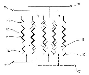
Fig. 1 shows a reactor for catalytic processing of
gaseous fluids. For the sake of clarity, here and in further
figures, the reaction housing is not shown.
A plurality of plates lo, which have a corrugated
structure, are arranged parallel to each other and define
channels 19. The plates 10 have a region 11 in which the
apposite sides of plates are provided with a catalyst 12,
213~~21
-9-
e.g., are coated. In addition, the plates 10 have regions 13
and 14, which are not provided with the catalyst, that is,
they do not have any coating. For delivering fluid, an inlet
15 and an inlet 16 and, for carrying away the products of the
reaction, an outlet 17 and an outlet 18 are provided.
The reactor functions as follows:
The fluid, which is delivered through the inlet 15,
is so divided that it f lows in the same direction only through
every other channel 19. The fluid, which is delivered through
the inlet 16, likewise flows through every other channel 19.
Thus, a counterflow is provided in two adjacent channels 19.
When the fluid passes through the region 11, provided, e.g.,
covered with a catalyst 12, a catalytic reaction takes place.
During this reaction, the heat is released which is
transferred to the fluid. When the fluid then passes through
the region 13, the heat is transferred to the plates 10. When
a non-processed and, thus, cold fluid flows in the adjacent
channel 19, it takes up the heat. So pre-heated fluid enters
the reaction zone of its channel 19 and there is catalytically
processed. Due to the exothermal reaction, the fluid is
heated further and then gives up the heat to the plates 10 in
the region 14.
2~3~2I
-10-
Because of the alternate flow of fluid in channels
19, an autothermal process takes place. Thus, each flow
channel has regions with different functions: in the first
portion, the fluid is heated up, the fluid reacts in a middle
portion and in a third portion, gives up heat to a fluid in
the adjacent channels. Thereby, it is insured that the fluid
is preheated to a respective pre-reaction temperature. At the
first activation of the reactor, an additional, single time,
preheating of the fluid may be required.
The heat flow in the plates can be changed and
thereby influenced by selection of the plate thickness, plate
material, and the configuration of the outer surface of a
plate.
Also, it is possible in a manner not shoran here, to
so equip, e.g., cover the plates 10 with the catalyst 12, that
regions with different temperatures and, therefore, different
functions, (heating, catalytic reaction, cooling) are
provided. When, e.g., a certain time period is required for
heating the fluid, then the first region is cooler, and in the
last region, which is also covered with the catalyst, no
further heating takes places, as due to the already taken
place catalytic reaction, no heat transformation takes place
in the purified fluid.
2~3~2~
-11-
Fig. 2 shows another embodiment of the reactor.
Here, likewise several plates 20, having corrugated structure,
are arranged parallel to each other and form channels 21. The
plates 20 have a region 22, with the opposite sides of the
plates 20 being provided, e.g., coated with the catalyst 22,
and a region 24, with no coating. Two respective non-adjacent
plates 20 are connected with each other so that two channels
24 surround a coherent bent reaction space. The reactor has
an inlet 25 for the fluid and an outlet 26 for the products.
The reactor functions as follows:
The fluid is delivered to the reactor through the
inlet 25 and is divided so that it flows in every other
channel 21. In the region 22 of the plates 20, a catalytic
reaction takes place. This reaction takes place during flow
of fluid in both directions, up and down. The fluid, which
was heated by the exothermal reaction, gives up heat to the
plates 20 in the region 24 when flowing downward. The heat,
which was released in the region 24 is transferred to the
upwardly flowing fluid in the adjacent channel 21, whereby
this fluid is pre-heated to a desired pre-reaction
temperature.
Fig. 3 shows a further embodiment of the reactor.
This reactor, contrary to that shown in Fig. 2, instead of the
213~~~~~
-12-
connection of two non-adjacent plates 20, has a collecting
channel 27. The channels 21 open into this collection
channel, whereby the fluid can flow back through different
channels.
In the embodiment shown here, an offtake 28 is
provided in the collecting channel 27 for conducting heat
energy away. Thereby, it is possible to carry away an
excessive heat energy generated during strong exothermal
catalytic reaction. However, the heat carrying away is
effected so that a sufficiently large amount of the heat
energy remains for heating of the plates 20 in the region 24.
In addition, two external pre-heating devices 29 and
30 are provided. These pre-heating devices are necessary for
an initial activation of the reactor for pre-heating the fluid
to the required reaction temperature. To this end,
alternatively, the pre-heating device 29 is provided at the
fluid inlet, and the pre-heating device 30 is provided in the
collecting channel 27.
The above-described embodiment examples are layed
out for an autothermal operation.
Fig. 4 shows an embodiment of a reactor which is
used at both strong exothermal and strong endothermal
2~.3~2~.
-13-
reactions. Here, channels 34, which are formed by pairs of
respective plates 32 defining a reaction space 31, form part
of a cooling or heating circuit 33. The plates 32 have a
region 36, coated with a catalyst 35, and lower and upper
regions 37 and 38, which are not coated.
The plates 32 are coated with the catalyst only on
the side thereof facing the reaction path.
The reactor functions as follows:
The fluid is delivered to the reactor through the
inlet 39 and is conducted into the reaction space 31. There,
the fluid is subjected to the already described catalytic
reaction in the region 36 and is carried away through the
outlet 40 dependent upon whether strong exothermal or strong
endothermal catalysis takes place, cooling or heating medium
is conducted through the channels 34. This results in heat
being supplied into or carried away from the reaction space
31. Thereby, the catalytic reaction is balanced. The regions
37 and 38 form, in this embodiment, already mentioned heating
or cooling zones for the fluid.
In another, not shown, embodiment example, the
regions 37 and 38, which are not provided, e.g., are not
coated with a catalyst, can be dispensed with, so that the
-~. 2~3~2~~
-14-
plates 32 are coated with the catalyst 35 along their entire
length. The cooling or heating then provided by the medium
that flows through the channels 34.
Another embodiment of the reactor is shown in Fig.
5. Here, the construction shown in Fig. 2 is combined with a
cooling or heating circuit 33. Thus, it is possible to use a
longest possible reaction path and thereby to extract
additional heat or to add additional heat, if needed.
Figs. 6-8 show different plate arrangements which do
not depend on general construction of the reactor.
Fig. 6 shows a perspective view of a plate
arrangement.
It is apparent that the plate 50 are alternatively
arranged at an angle one above the other. The plates 50 are
supported here on their bulging 51 defining the corrugated
structure.
Such an optimal support simultaneously provides for
good stability, even with very thin walls. Because the thin
walls insure good heat conductivity, an optimal construction
is thereby obtained.
213~~1
-15-
The plates 50 form channels 52. The channel 52,
because of the bulgings 51, do not extend at the same level.
These obstructions lead to an increased turbulence in the
fluid stream and/or in the stream of cooling or heating medium
and, as a result, in a better performance of the whole
apparatus.
As a displacement angle, an angle between 0° and 90°
can be used.
Further, as Fig. 7 shows, it is possible to arrange
the corrugated structures so that they are located one beneath
the other. The plates 60 are so arranged that they form a
through channel 61. Between the plates, there are provided
additional supports (not shown).
As further shown in Fig. 8, it is advantageous when
the plates 20 and 21 have a different shape and differ from
each other in height and form corrugated structures with a
different spacing between corrugation.
The invention is not limited to the shown
embodiments, but rather relates to all catalyst-containing
reactors the heating and/or cooling zones of which can be
associated with the processed fluid.
-16-
It is also within the scope of the invention, when
the shown catalyst regions 11, 22, 36 are not continuously
provided with a catalyst, coated therewith, but also have
catalyst-free regions. Thereby, a more precise heating during
conducting the entire process is possible.
Generally, it is possible to provide the fluid paths
with a catalyst in any arbitrary manner. For example, the
coating of the walls with a catalyst mass can be eliminated
and instead, a catalyst-covered structure, e.g., a grid, or a
catalyst in bulk can be provided in the fluid path.