Sélection de la langue

Search

Sommaire du brevet 2134999 

Énoncé de désistement de responsabilité concernant l'information provenant de tiers

Une partie des informations de ce site Web a été fournie par des sources externes. Le gouvernement du Canada n'assume aucune responsabilité concernant la précision, l'actualité ou la fiabilité des informations fournies par les sources externes. Les utilisateurs qui désirent employer cette information devraient consulter directement la source des informations. Le contenu fourni par les sources externes n'est pas assujetti aux exigences sur les langues officielles, la protection des renseignements personnels et l'accessibilité.

Disponibilité de l'Abrégé et des Revendications

L'apparition de différences dans le texte et l'image des Revendications et de l'Abrégé dépend du moment auquel le document est publié. Les textes des Revendications et de l'Abrégé sont affichés :

  • lorsque la demande peut être examinée par le public;
  • lorsque le brevet est émis (délivrance).
(12) Brevet: (11) CA 2134999
(54) Titre français: PROTHESE ARTICULAIRE
(54) Titre anglais: PROSTHETIC JOINT
Statut: Périmé
Données bibliographiques
(51) Classification internationale des brevets (CIB):
  • A61F 2/64 (2006.01)
  • A61F 2/68 (2006.01)
  • A61F 2/50 (2006.01)
  • A61F 2/74 (2006.01)
(72) Inventeurs :
  • KRUKENBERG, MANFRED (Allemagne)
(73) Titulaires :
  • OTTO BOCK HEALTHCARE GMBH (Allemagne)
(71) Demandeurs :
  • OTTO BOCK ORTHOPADISCHE INDUSTRIE BESITZ-UND VERWALTUNGS-KOMMANDITGESELLSCHAFT (Allemagne)
(74) Agent: KIRBY EADES GALE BAKER
(74) Co-agent:
(45) Délivré: 2001-01-09
(22) Date de dépôt: 1994-11-03
(41) Mise à la disponibilité du public: 1995-05-16
Requête d'examen: 1996-12-17
Licence disponible: S.O.
(25) Langue des documents déposés: Anglais

Traité de coopération en matière de brevets (PCT): Non

(30) Données de priorité de la demande:
Numéro de la demande Pays / territoire Date
P 43 38 946.5 Allemagne 1993-11-15

Abrégés

Abrégé français

La présente invention concerne une prothèse articulaire, en particulier une prothèse de genou ou de hanche, avec une partie d'articulation supérieure (1), une partie d'articulation inférieure (2), un axe d'articulation (3) reliant ces deux parties d'articulation (1, 2) en pivot l'une avec l'autre, et relié en rotation avec une partie d'articulation (1), et un amortissement du balancement d'articulation. Pour arriver, en particulier, à une conception plus compacte de la prothèse, il est proposé conformément à l'invention que l'amortissement soit intégré dans l'une (2) des deux parties d'articulation (1, 2) et agisse directement sur l'axe d'articulation (3) relié de manière non rotative à l'autre partie d'articulation (1).


Abrégé anglais

The invention relates to a prosthetic joint, especially a knee or hip joint, with an upper joint part (1), a lower joint part (2), a joint axle (3) connecting these two joint parts (1, 2) pivotably with one another and connected rotatably with one joint part (1), and a damping of the joint swing. To achieve in particular a more compact design of the joint, it is proposed according to the invention that the damping be integrated into one (2) of the two joint parts (1, 2) and act directly on joint axle (3) nonrotatably connected with the other joint part (1).

Revendications

Note : Les revendications sont présentées dans la langue officielle dans laquelle elles ont été soumises.


Claims


1. A prosthetic joint having an upper joint part, a
lower joint part, a joint axle joining these two
joint parts pivotably with one another and
nonrotatably connected with one of said joint parts,
and a damper of the joint swing, wherein:
a) the damper is integrated into one of the two
joint parts and acts directly on the joint axle
nonrotatably connected with the other joint
part;
b) the damper has an enclosed displacement chamber
concentrically surrounding the joint axle at
least partially or over its circumference, said
chamber being divided by the joint axle, made
in the form of a rotary piston, into two
sectional chambers;
c) sectional chambers of the displacement chamber
are connected together by two throttle-check
valves connected in parallel and acting in
opposite directions;
d) both throttle-check valves are controllable
from the exterior separately from one another;
and
e) a force loading the joint causes a predefined
closure of one of said throttle-check valves.
2. Prosthetic joint according to Claim 1 wherein
control of the throttle-check valves is provided by
a throttle rod, located displaceably lengthwise in
said lower joint part.


7


3. Prosthetic joint according to Claim 2 wherein a
manually adjustable knurled screw or the like is
provided for the displacement of the throttle rod.
4. Prosthetic joint according to Claim 1, Claim 2 or
Claim 3 wherein said rotary piston comprises a
rectangular piston plate which abuts the two ends
and the cylindrical inside wall of displacement
chamber by a sealing frame.
5. Prosthetic joint according to Claim 4 wherein the
sealing frame is held in place by a retainer screwed
to piston plate.
6. Prosthetic joint according to Claim 1, Claim 2,
Claim 3, Claim 4 or Claim 5 wherein a rotary piston
seal sealing the displacement chamber from the
exterior is located outside of a rotary piston
bearing.
7. Prosthetic joint according to Claim 1, Claim 2,
Claim 3, Claim 4, Claim 5 or Claim 6 wherein two
bores are provided for mounting the two
throttle-check valves in the joint part receiving
displacement chamber, said bores being sealed from
the exterior by a sealing plug.
8. Prosthetic joint according to Claim 1, Claim 2,
Claim 3, Claim 4, Claim 5, Claim 6 or Claim 7
wherein the damper medium is a hydraulic oil with
high lubricating properties.
9. Prosthetic joint according to Claim 1, Claim 2,
Claim 3, Claim 4, Claim 5, Claim 6, Claim 7 or
Claim 8 wherein upper joint part abuts with its
partially cylindrical underside, the cylindrical
surface of lower joint part provided eccentrically
with respect to the upper joint part.

Description

Note : Les descriptions sont présentées dans la langue officielle dans laquelle elles ont été soumises.


21 3+999
Prosthetic Joint
The invention relates to a prosthetic joint, especially a
knee or hip joint, with an upper joint part, a lower
joint part, a joint axle connecting these two joint parts
together in pivotable fashion, and nonrotatably connected
with one joint part, and a damping of the joint swing.
Damping a knee joint hydraulically is known. A hydraulic
damping cylinder located outside the joint is provided
for this purpose, said cylinder being articulated at one
end on the lower joint part and acting with its piston
rod on a lever connected with the upper joint part.
Summary of the Invention
A goal of the invention is to improve known designs.
In accordance with one aspect of the present invention
there is provided a prosthetic joint having an upper
joint part, a lower joint part, a joint axle joining
these two joint parts pivotably with one another and
nonrotatably connected with one of said joint parts, and
a damper of the joint swing, wherein: a) the damper is
integrated into one of the two joint parts and acts
directly on the joint axle nonrotatably connected with
the other joint part; b) the damper has an enclosed
displacement chamber concentrically surrounding the joint
axle at least partially or over its circumference, said
chamber being divided by the joint axle, made in the form
of a rotary piston, into two sectional chambers;
c) sectional chambers of the displacement chamber are
connected together by two throttle-check valves connected
in parallel and acting in opposite directions; d) both
throttle-check valves are controllable from the exterior
separately from one another; and e) a force loading the
joint causes a predefined closure of one of said
throttle-check valves.


21 34999
2
The design according to the invention, in its application
as a knee joint, in addition to the known braking knee,
permits a swing phase control in which the swing
resistance can be adjusted separately for flexure and
extension.
The throttles can basically be controlled mechanically or
by an electrical positioning drive. It is advantageous
according to the invention for a throttle to be
controlled by an axially displaceable throttle rod whose
displacement can be effected for example by a manually
adjustable knurled screw or the like.
Particularly in a prosthetic joint designed as a knee
joint, it is advantageous for a force loading the joint
to cause a predefined closure of the bending throttle.
This can be accomplished in the design in the form of a
telescopic, force, or moment control.
Preferably, the rotary piston has a rectangular piston
plate abutting the two ends and the cylindrical inside
wall of the enclosed displacement chamber by a sealing
frame. The latter can preferably be held in place by a
retainer screwed to the piston plate. This results in a
displacement chamber enclosed on all sides with a single
defined leak provided in the area of the rotary piston
seal. It is advantageous in this regard for the rotary
piston seal sealing the displacement chamber from the
exterior to be located outside the rotary piston bearing.
Lubrication of the rotary piston bearing is provided by
the pressure prevailing the displacement chamber, in
other words by the hydraulic oil which should therefore
have superior lubricating properties.
Additional features of the invention will be explained in
greater detail in
1.


21 34999
3
conjunction with further advantages of the invention with
reference to an embodiment.
The drawing shows one embodiment of the invention as an
example.
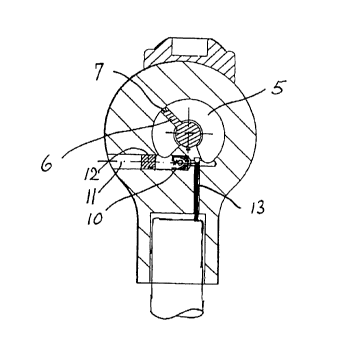
Figure 1 shows a knee joint in a side view;
Figure 2 is the representation in Figure 1 in an end view;
Figure 3 is the representation in Figure 1 in a top view;
Figure 4 is a lengthwise section along line A-A in Figure 2;
Figure 5 is a lengthwise section along line C-C in Figure 2;
and
Figure 6 is a cross section along line B-B in Figure 1.
A knee joint is shown as an example of a prosthetic joint,
said knee joint consisting of an upper joint part 1 and a
lower joint part 2 located slightly eccentrically with
respect to the latter. The pivotable connection of the two
joint parts l, 2 is provided by a joint axle 3 nonrotatably
connected with upper joint part 1. Upper joint part 1 abuts
the cylindrical surface 4 of lower joint part 2 with its
partially cylindrical lower side. Because of the eccentric
arrangement of the two parts with respect to one another,
during a joint swing upper joint part 1 rolls with its lower
side on cylindrical surface 4, which therefore serves as a
joint buffer over its entire surface. A separate joint stop
is therefore unnecessary.
To damp the joint swing, in the embodiment shown hydraulic
damping is provided that is directly integrated into lower


_. 21 34999
4
joint part 2, said damping acting directly on joint axle 3,
Hydraulic damping comprises an enclosed displacement chamber
surrounding joint axle 3 over its circumference partially
concentrically, said chamber being divided by joint axle 3
in the form of a rotary piston into two sectional chambers
5a, 5b. For this purpose, joint axle~3 is provided with a
rectangular piston plate 6 extending in the axial and radial
directions, said plate abutting in sealing fashion the two
end walls of displacement chamber 5 with its two radially
extending end edges and abutting the cylindrical inside wall
of displacement chamber 5 with its axially extending
lengthwise edge. Preferably this seal is provided by a
sealing frame 7, mounted on piston plate 6 by means of a
retainer screwed to piston plate 6 and not shown in the
drawing.
Displacement chamber 5 is sealed from the exterior by a
rotary piston seal 8 located outside rotary piston bearing
9. Lubrication is provided by the pressure prevailing in
the displacement chamber 5, with displacement chamber 5
preferablx being filled with a hydraulic oil with superior
lubricating properties.
Sectional chambers 5a, 5b are connected together by two
throttle-check valves 10 connected in parallel and acting in
opposite directions. These valves are located in two bores
11 provided side by side in lower joint part 2, said bores
running perpendicularly to joint axle 3 and being sealed
from the exterior by sealing plugs 12.
A throttle rod 13 is provided to control the throttle of
each throttle-check valve 10 in the embodiment shown, said
rod being displaceable lengthwise by an adjusting device not
shown in greater detail, for, example a manually operated
knurled screw, and projecting with its upper free end shown
r


_. 213~99~
in Figure 5 to a greater or lesser depth into the flow cross
section of the flow connection between the two sectional
chambers 5a and 5b. The possibility of separate adjustment
of the two throttle rods 13 allows the swing resistance to
be adjusted separately for flexure and extension. It is
also advantageous in this regard for loading of the knee to
result in closure of the bending throttle. This is ensured
by a telescopic, force, or moment control not shown in the
drawing.

Dessin représentatif
Une figure unique qui représente un dessin illustrant l'invention.
États administratifs

Pour une meilleure compréhension de l'état de la demande ou brevet qui figure sur cette page, la rubrique Mise en garde , et les descriptions de Brevet , États administratifs , Taxes périodiques et Historique des paiements devraient être consultées.

États administratifs

Titre Date
Date de délivrance prévu 2001-01-09
(22) Dépôt 1994-11-03
(41) Mise à la disponibilité du public 1995-05-16
Requête d'examen 1996-12-17
(45) Délivré 2001-01-09
Expiré 2014-11-03

Historique d'abandonnement

Il n'y a pas d'historique d'abandonnement

Historique des paiements

Type de taxes Anniversaire Échéance Montant payé Date payée
Le dépôt d'une demande de brevet 0,00 $ 1994-11-03
Enregistrement de documents 0,00 $ 1995-05-11
Taxe de maintien en état - Demande - nouvelle loi 2 1996-11-04 100,00 $ 1996-10-08
Requête d'examen 400,00 $ 1996-12-17
Taxe de maintien en état - Demande - nouvelle loi 3 1997-11-03 100,00 $ 1997-10-07
Taxe de maintien en état - Demande - nouvelle loi 4 1998-11-03 100,00 $ 1998-08-24
Taxe de maintien en état - Demande - nouvelle loi 5 1999-11-03 150,00 $ 1999-10-19
Taxe finale 300,00 $ 2000-09-06
Taxe de maintien en état - Demande - nouvelle loi 6 2000-11-03 150,00 $ 2000-10-23
Taxe de maintien en état - brevet - nouvelle loi 7 2001-11-05 150,00 $ 2001-10-09
Taxe de maintien en état - brevet - nouvelle loi 8 2002-11-04 150,00 $ 2002-10-10
Enregistrement de documents 50,00 $ 2003-05-07
Taxe de maintien en état - brevet - nouvelle loi 9 2003-11-03 150,00 $ 2003-10-14
Taxe de maintien en état - brevet - nouvelle loi 10 2004-11-03 250,00 $ 2004-10-15
Taxe de maintien en état - brevet - nouvelle loi 11 2005-11-03 250,00 $ 2005-09-30
Taxe de maintien en état - brevet - nouvelle loi 12 2006-11-03 250,00 $ 2006-10-16
Taxe de maintien en état - brevet - nouvelle loi 13 2007-11-05 250,00 $ 2007-10-25
Taxe de maintien en état - brevet - nouvelle loi 14 2008-11-03 250,00 $ 2008-10-21
Taxe de maintien en état - brevet - nouvelle loi 15 2009-11-03 450,00 $ 2009-10-20
Taxe de maintien en état - brevet - nouvelle loi 16 2010-11-03 450,00 $ 2010-10-20
Taxe de maintien en état - brevet - nouvelle loi 17 2011-11-03 450,00 $ 2011-10-24
Taxe de maintien en état - brevet - nouvelle loi 18 2012-11-05 450,00 $ 2012-10-22
Taxe de maintien en état - brevet - nouvelle loi 19 2013-11-04 450,00 $ 2013-10-21
Titulaires au dossier

Les titulaires actuels et antérieures au dossier sont affichés en ordre alphabétique.

Titulaires actuels au dossier
OTTO BOCK HEALTHCARE GMBH
Titulaires antérieures au dossier
KRUKENBERG, MANFRED
OTTO BOCK ORTHOPADISCHE INDUSTRIE BESITZ-UND VERWALTUNGS-KOMMANDITGESELLSCHAFT
Les propriétaires antérieurs qui ne figurent pas dans la liste des « Propriétaires au dossier » apparaîtront dans d'autres documents au dossier.
Documents

Pour visionner les fichiers sélectionnés, entrer le code reCAPTCHA :


Pour visualiser une image, cliquer sur un lien dans la colonne description du document. Pour télécharger l'image (les images), cliquer l'une ou plusieurs cases à cocher dans la première colonne et ensuite cliquer sur le bouton "Télécharger sélection en format PDF (archive Zip)" ou le bouton "Télécharger sélection (en un fichier PDF fusionné)".

Liste des documents de brevet publiés et non publiés sur la BDBC .

Si vous avez des difficultés à accéder au contenu, veuillez communiquer avec le Centre de services à la clientèle au 1-866-997-1936, ou envoyer un courriel au Centre de service à la clientèle de l'OPIC.


Description du
Document 
Date
(yyyy-mm-dd) 
Nombre de pages   Taille de l'image (Ko) 
Page couverture 1995-10-22 1 77
Dessins représentatifs 2000-12-07 1 8
Abrégé 1995-10-22 1 80
Revendications 1995-10-22 2 156
Description 1995-10-22 5 478
Abrégé 2000-04-05 1 16
Description 2000-04-05 5 192
Revendications 2000-04-05 2 70
Dessins 1995-10-22 2 41
Page couverture 2000-12-07 1 31
Dessins représentatifs 2000-04-05 1 8
Cession 2003-05-07 3 79
Correspondance 2000-09-06 1 35
Lettre du bureau 1997-02-11 1 38
Correspondance de la poursuite 2000-03-08 2 57
Demande d'examen 1999-11-18 2 49
Correspondance de la poursuite 1996-12-17 1 50
Correspondance de la poursuite 1996-12-17 8 527
Correspondance de la poursuite 1994-11-03 11 376