Sélection de la langue

Search

Sommaire du brevet 2138694 

Énoncé de désistement de responsabilité concernant l'information provenant de tiers

Une partie des informations de ce site Web a été fournie par des sources externes. Le gouvernement du Canada n'assume aucune responsabilité concernant la précision, l'actualité ou la fiabilité des informations fournies par les sources externes. Les utilisateurs qui désirent employer cette information devraient consulter directement la source des informations. Le contenu fourni par les sources externes n'est pas assujetti aux exigences sur les langues officielles, la protection des renseignements personnels et l'accessibilité.

Disponibilité de l'Abrégé et des Revendications

L'apparition de différences dans le texte et l'image des Revendications et de l'Abrégé dépend du moment auquel le document est publié. Les textes des Revendications et de l'Abrégé sont affichés :

  • lorsque la demande peut être examinée par le public;
  • lorsque le brevet est émis (délivrance).
(12) Brevet: (11) CA 2138694
(54) Titre français: CARTE D'ORDINATEUR PERSONNEL MUNIE D'UN DISPOSITIF ELECTRONIQUE
(54) Titre anglais: IC CARD HAVING AN ELECTRONIC APPARATUS
Statut: Réputé périmé
Données bibliographiques
(51) Classification internationale des brevets (CIB):
  • G06F 1/16 (2006.01)
  • H05K 5/02 (2006.01)
(72) Inventeurs :
  • KOBAYASHI, FUMIYUKI (Japon)
  • DEGUCHI, MANABU (Japon)
(73) Titulaires :
  • NEC CORPORATION (Japon)
(71) Demandeurs :
(74) Agent: G. RONALD BELL & ASSOCIATES
(74) Co-agent:
(45) Délivré: 1998-08-18
(22) Date de dépôt: 1994-12-21
(41) Mise à la disponibilité du public: 1995-06-29
Requête d'examen: 1994-12-21
Licence disponible: S.O.
(25) Langue des documents déposés: Anglais

Traité de coopération en matière de brevets (PCT): Non

(30) Données de priorité de la demande:
Numéro de la demande Pays / territoire Date
335277/1993 Japon 1993-12-28
335278/1993 Japon 1993-12-28

Abrégés

Abrégé français

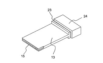
L'invention est une carte de circuit imprimé qui est constituée d'une section carte et d'une section boîtier intégrées dans une même structure, un circuit étant monté à l'une des extrémités de la section carte. L'autre extrémité de cette carte porte un connecteur d'interface femelle et la pièce de connexion de la section carte et de la section boîtier contient un élément protecteur élastique. Quand la section carte est insérée dans l'ouverture d'un terminal de données compact et que le connecteur d'interface femelle est fixé au connecteur d'interface mâle interne du terminal, la carte de circuit intégré de l'invention devient opérationnelle. Dans cette configuration, quand la carte de l'invention est insérée dans le terminal, l'élément protecteur empêche la pièce de connexion d'être endommagée par les forces exercées sur la section boîtier.


Abrégé anglais


A PC card consists of a PC card section and a casing
section with a built-in electronic circuit provided at one
end of the PC card section, and the PC card section and
the casing section are integrated into a single structure.
At the other end of the PC card section is provided a
female interface connector, and in the connecting part
between the PC card section and the casing section is
arranged an elastic protective member. By inserting the
PC card section into a slit section of a compact data
terminal and connecting the female interface connector
to a male interface connector, the PC card is actuated.
In this configuration, when the PC card is inserted into
the terminal, the protective member prevents the connecting
part from being damaged by any force working on the casing
section.

Revendications

Note : Les revendications sont présentées dans la langue officielle dans laquelle elles ont été soumises.


- 9 -

THE EMBODIMENTS OF THE INVENTION IN WHICH AN EXCLUSIVE
PROPERTY OR PRIVILEGE IS CLAIMED ARE DEFINED AS FOLLOWS:


1. An integrated circuit (IC) card having an
electronic apparatus, the card comprising:
an IC card section having an integrated circuit;
an electronic apparatus section connected at one end
of the IC card section; and,
an elastic protective member in the vicinity of the
connecting point between the electronic apparatus section and
the IC card section.


2. An IC card according to claim 1, wherein the
protective member is detachable from the IC card.


3. An IC card according to claim 1 or 2, wherein a
connector is provided at the other end of the IC card section
for connection to an external terminal.


4. An IC card according to claim 1, 2, or 3, wherein
the IC card section and the electronic device section are
connected to each other by a hinge section.


5. An IC card according to claim 4, further
comprising an elastic protective section in the vicinity of
the hinge section.


Description

Note : Les descriptions sont présentées dans la langue officielle dans laquelle elles ont été soumises.


2138~9~


IC CARD HAVING AN ELECTRONIC APPARATUS


BACKGROUWD OF THE INVENTION
The present invention relates to an IC card with a
built-in integrated circuit, and more particularly to an
IC card having an electronic apparatus, such as a radio
modem.
Conventional IC cards having an electronic apparatus
are used as connected to various compact data terminals
such as a personal computer. For instance, an IC card
using a radio modem as electronic apparatus can transfer
by radio the data in the personal computer. Such IC cards
are often referred to as personal computer cards or PCMICI
(Personal Computer Memory Card International Association)
cards, and will be hereinafter called PC cards in this
specification.
A compact data terminal has a slit section into which
a card can be inserted and a male interface connector within
the slit section.
On the other hand, a PC card comprises a PC card
section and a casing section provided at one end of the
PC card section and having a built-in electronic circuit,
and the PC card section and the casing section are
integrated into a single structure. At the other end
o~ the PC card section is provided a female interface
connector.


21 38694
-- 2


Therefore, by inserting the PC card section into the
slit section and thereby connecting the male and female
interface connectors, the PC card can be actuated to become
ready for use.
However, this PC card according to the prior art
involves the problem that, because, when the PC card is
fitted to a compact data terminal, a gap is left between
the electronic apparatus of the card and the terminal, a
stress will arise in the vicinity of the connecting part
between the PC card section and the casing section and
damage will occur in and around the part if, for instance,
a load is applied from above on the casing section, as
will be described in more detail below.


SUMMARY OF THE INVENTION
An object of the present invention, therefore, is to
obviate the aforementioned disadvantage, and to provide a
PC card which will not be damaged even if a load is applied
to it when inserted into a terminal.
~ccording to the invention, there is provided an IC
card having an electronic apparatus, the card comprising an
IC card section having an integrated circuit, an electronic
apparatus section connected at one end of the IC card
section, and an elastic protective member in the vicinity
of the connecting point between the electronic apparatus
section and the IC card section.


2138694


BRIEF DESCRIPTION OF THE DRAWINGS
The above-mentioned and other objects, features and
advantages of the present invention will become more
apparent from the following detailed description when
taken in conjunction with the accompanying drawings,
wherein:
Figs. 1 and 2 are illustrations for explaining a
problem of the conventional PC card;
Figs. 3 and 4 show side views of a first embodiment
of the present invention;
Figs. 5 - 7 show side views of a second embodiment
of the present invention;
Figs. 8 - 10 show side views of a third embodiment
of the present invention; and
lS Fig. 11 shows a detail of a hinge section.


DETAILED DESCRIPTION OF THE PREFERRED EMBODIl~ENTS
First, to facilitate better understanding of the
present invention, the prior art will be described with
reference to Figs. 1 and 2.
In Figs. 1 and 2, a compact data terminal 11 has
a slit section 16 into which a card section 13 can be
inserted and a male interface connector 17 within the
slit section 16.
On the other hand, a card-integrated electronic
apparatus 31 comprises a PC card section 13 and a casing

213869~

,- 4 -


section 32 provided at one end of the PC card section 13
and having a built-in electronic circuit. The PC card
section 13 and the casing section 32 are integrated into
a single structure. At the other end of the PC card
section 13 is provided a female interface connector 15.
By inserting the PC card section 13 into the slit section
16 and thereby connecting the male interface connector 17
and the female interface connector 15, the PC card-
integrated electronic apparatus 31 can be actuated to
become ready for use.
However, this PC card according to the prior art
involves the problem that, because, when the PC card is
fitted to the compact data terminal 11, a gap a as shown
in Fig. 2 is left between the electronic apparatus of the
card and the terminal, a stress will arise in the vicinity
of the connecting part between the PC card section 13 and
the casing section 32 and damage will occur in and around
the part if, for instance, a load P is applied on the
casing section 32 in the direction represented by the
arrow.
Figs. 3 and 4 are profiles (with a partial cross-
sectional view) illustrating a first preferred embodiment
of the present invention. A PC card 12 to be fitted to
and used in a compact data terminal 11 has a shape in
which a PC card section 13 and a casing section 14 are
combined. At one end of the PC card section 13 is provided
a female interface connector 15.


213~6'~q


On the other hand, the compact data terminal 11 has a
slit section 16, and within the slit section 16 is provided
a male interface connector 17 (Fig. 3).
By inserting the PC card section 13 into the slit
section 16 and thereby connecting the male interface
connector 17 of the compact data terminal 11 and the
female interface connector 15 of the PC card section 13,
the card-integrated electronic apparatus 12 be actuated
to become ready for use (Fig. 4). In the connecting part
between the PC card section 13 and the casing section 14
of the PC card 12 is arranged a protective member 18 made
of an elastic material such as rubber. The protective
member 18 has a thickness substantial equal to the gap
which is left between the compact data terminal 11 and
the casing section 14 when the PC card section 13 of the
card-integrated electronic apparatus 12 is inserted, and
fixed to the peripheries of the connecting faces of the
casing section 14 and the PC card section 13.
Next will be described a second preferred embodiment
of the invention with reference to Fig. 5.
The second embodiment differs from the first embodiment
in that the protective member is detachable from the card-
integrated electronic apparatus. The protective member 21
here, formed substantially in a frame shape, is engaged
while being pressed against a groove section 23 formed in
a headband shape around the surface of a casing section 24


213869~


of this card-integrated electronic apparatus 2, and fixed
to the casing section 24.
Both in the first and second embodiments, the gap
- left between the compact data terminal 11 and the casing
section 14 or 24 of the PC card-integrated electronic
apparatus 12 or 22 can be respectively filled with the
protective member 18 or 21.
Therefore, the stress arising in and around the
connecting part between the PC card section 13 and the
casing section 14 when the load P is applied on the casing
section 14 of the card-integrated electronic apparatus 12
can be eased, and damage can be thereby prevented.
Figs. 8 through 10 illustrate a third preferred
embodiment of the present invention. This third embodiment
is a PC card which not only is protected from damage but
also can be inserted into a terminal irrespective of
whether the front or back face of the inserting section
of the PC card is upward.
A PC card 12, which is the third embodiment of the
invention, has a PC card section 13 having a female
interface connector 15 at one of its ends and a casing
section 14 having an electronic circuit inside. The PC
card section 13 and the casing section 14 are connected
to each other by a swingable hinge section 19. In this
example, the illustration of the protective member is
dispensed with in order to highlight the hinge, which is
the particular feature of this third embodiment.


2138694


The PC card section 13 and the casing section 14 are
also connected electrically by a connecting member such
as a flexible printed board. Further by using within the
hinge section 19 a bush member utilizing elasticity or
frictional force, the PC card section 13 and the casing
section 14 are enabled to be held in any desired angle
of swing.
Referring to Fig. 9, whereas there is no unification
as to whether the front face of the male interface
connector 17 within the small data terminal 11 should be
upward or downward, even in a compact data terminal llC
into which, as illustrated in Fig. 10, the PC card-
integrated electronic apparatus 12 is to be inserted
in the reverse direction to that in Fig. 9, the casing
section 14 can be prevented from projecting from the
bottom of the compact data terminal llC by swinging
this casing section 14.
Referring to Fig. 11, the PC card section 13 is
electrically connected to the casing section 14 by a
flexible print wire circuit sheet 42. A bush number 41
is used to hold the PC card section 13 and the casins
section 14 in any desired angle of swing. The bush
member includes a first element 43 and a second element
44 which are connected each other through a shaft.
Each of the two elements 43 and 44 rotates independently
around the shaft using frictional force. Therefore, when


~138694


the elements 44 and 43 are fixed to the PC card section 13
and the casing section 14, respectively, the two sections
13 and 14 are connected each other by the bush member, and
the two sections can be held in any angle of swing by the
bush member 41.


Dessin représentatif
Une figure unique qui représente un dessin illustrant l'invention.
États administratifs

Pour une meilleure compréhension de l'état de la demande ou brevet qui figure sur cette page, la rubrique Mise en garde , et les descriptions de Brevet , États administratifs , Taxes périodiques et Historique des paiements devraient être consultées.

États administratifs

Titre Date
Date de délivrance prévu 1998-08-18
(22) Dépôt 1994-12-21
Requête d'examen 1994-12-21
(41) Mise à la disponibilité du public 1995-06-29
(45) Délivré 1998-08-18
Réputé périmé 2002-12-23

Historique d'abandonnement

Il n'y a pas d'historique d'abandonnement

Historique des paiements

Type de taxes Anniversaire Échéance Montant payé Date payée
Le dépôt d'une demande de brevet 0,00 $ 1994-12-21
Enregistrement de documents 0,00 $ 1995-06-29
Taxe de maintien en état - Demande - nouvelle loi 2 1996-12-23 100,00 $ 1996-12-13
Taxe de maintien en état - Demande - nouvelle loi 3 1997-12-22 100,00 $ 1997-12-12
Taxe finale 300,00 $ 1998-04-16
Taxe de maintien en état - brevet - nouvelle loi 4 1998-12-21 100,00 $ 1998-12-11
Taxe de maintien en état - brevet - nouvelle loi 5 1999-12-21 150,00 $ 1999-12-09
Taxe de maintien en état - brevet - nouvelle loi 6 2000-12-21 150,00 $ 2000-12-11
Titulaires au dossier

Les titulaires actuels et antérieures au dossier sont affichés en ordre alphabétique.

Titulaires actuels au dossier
NEC CORPORATION
Titulaires antérieures au dossier
DEGUCHI, MANABU
KOBAYASHI, FUMIYUKI
Les propriétaires antérieurs qui ne figurent pas dans la liste des « Propriétaires au dossier » apparaîtront dans d'autres documents au dossier.
Documents

Pour visionner les fichiers sélectionnés, entrer le code reCAPTCHA :


Pour visualiser une image, cliquer sur un lien dans la colonne description du document. Pour télécharger l'image (les images), cliquer l'une ou plusieurs cases à cocher dans la première colonne et ensuite cliquer sur le bouton "Télécharger sélection en format PDF (archive Zip)" ou le bouton "Télécharger sélection (en un fichier PDF fusionné)".

Liste des documents de brevet publiés et non publiés sur la BDBC .

Si vous avez des difficultés à accéder au contenu, veuillez communiquer avec le Centre de services à la clientèle au 1-866-997-1936, ou envoyer un courriel au Centre de service à la clientèle de l'OPIC.


Description du
Document 
Date
(yyyy-mm-dd) 
Nombre de pages   Taille de l'image (Ko) 
Description 1997-07-16 8 245
Revendications 1997-07-16 1 26
Page couverture 1995-08-23 1 15
Abrégé 1995-06-29 1 22
Description 1995-06-29 8 244
Revendications 1995-06-29 2 30
Page couverture 1998-08-10 1 48
Dessins 1995-06-29 5 67
Dessins représentatifs 1998-06-10 1 4
Dessins représentatifs 1998-08-10 1 4
Taxes 1999-12-09 1 45
Taxes 2000-12-11 1 47
Correspondance 1998-04-16 1 40
Taxes 1998-12-11 1 47
Taxes 1997-12-12 1 44
Taxes 1996-12-13 1 47
Correspondance de la poursuite 1994-12-21 6 198
Lettre du bureau 1995-07-21 1 34
Correspondance de la poursuite 1997-04-30 6 100
Demande d'examen 1997-02-20 2 64
Correspondance de la poursuite 1997-06-10 2 46