Note : Les descriptions sont présentées dans la langue officielle dans laquelle elles ont été soumises.
P-2366
214130
STEROID ELUTING STITCH-IN CHRONTC CARDIAC LEAD
FIELD OF THE INVENTION
This invention relates to an electrical lead used
to provide electrical signals to a tissue, and especially a
human organ, such as a heart, and more particularly, to a
chronically implanted steroid eluting cardiac lead.
BACKGROUND OF THE INVENTION
Electrical stimulation of body tissue and organs
is often used as a method of treating various pathological
conditions. Such stimulation generally entails making an
electrical contact between body tissue and an electrical
pulse generator through use of one or more stimulation leads.
Various lead structures and various techniques for implanting
these lead structures into body tissue and particularly the
heart have been developed.
For example, a transvenous endocardial lead
establishes electrical contact between an electrical pulse
generator and heart through placement of a lead in the venous
system. Specifically, an electrical lead is passed through
a vein, with the assistance of a fluoroscope, into the heart
where it is held in contact with the endocardium by the
trabeculae of the heart chamber, such as the ventricle.
There are, however, disadvantages to this type of
lead, including: possible damage to the vein, such as
perforation or laceration during insertion; possible failure
to securely attach and maintain electrical contact with the
heart; possible perforation of the heart wall by the lead;
and because direct visual inspection of the lead placement is
not possible, possible improper lead placement in the heart.
Besides these possible problems, there are
additional situations in which the installation of a
transvenous endocardial pacing lead is either not feasible or
not recommended. These situations include the case when the
vein which would be used is damaged or too small, or the
situation in which a physical or anatomical anomaly prevents
the placement of a transvenous endocardial lead within the
heart, such as the presence of an artificial heart valve.
P-2366
2 214~.53~
In particular a transvenous endocardial lead is
often either not feasible or recommended in children. One
problem presented by use of a transvenous endocardial lead
stems from the growth a child undergoes. Specifically, upon
chronic implantation of a transvenous lead the lead body is
subject to fibrotic encapsulation within the venous system.
This encapsulation fixes the lead body in place, especially
relative.to the walls of the venous system. Over time, as
the child grows the venous system elongates. Because the
lead is fixed by fibrotic growth, as the venous system
elongates the lead electrode will be pulled or dislodged from
effective contact with the endocardium. In addition, because
the venous system of a child is smaller than an adult, it is
less tolerant of the partial occluding of a vein by a
transvenous lead. In these cases use of an myocardial lead
applied from the epicardium is often indicated or preferred.
A myocardial lead offers a significant advantage to
a transvenous endocardial lead with regards to children.
Because a myocardial lead is attached to the heart not
through the venous system but rather through a thoracic
access, a sufficient amount of spare lead length to
accommodate growth may be located or looped within the
thoracic cavity. In addition a myocardial lead does not even
partially occlude a part of the relatively small venous
system of a child.
A number of different myocardial leads have been
developed, as have various techniques for implanting them
within the myocardial tissue of the heart. Typically,
myocardial leads are attached from the exterior of the heart
through a thoracic access.
One form of such lead is a screw-in lead. This
lead consists of a rigid helical coil which is used to fix
the electrode to the myocardial tissue. Examples of such a
lead may be found in U.S. Patent No. 5,154,183 to
Kreyenhagen et al., U.S. Patent No. 5,143,090 to butcher et
al., U.S. Patent No. 5,085,218 to Heil Jr. et al., and U.S.
Patent No. 4,010,758 to Rockland et al. One problem which
has been found to exist with such leads, however, is the
inflammatory tissue reaction (or foreign body response) of
p_2366
3
:v
the tissue to the device and especially the rigid helix.
Inflammatory tissue reaction is caused, in part, from the
presence of a foreign object within the tissue. It has been
found that the presence of a rigid structure within the
myocardium chronically creates at least some of the
immediately surrounding myocardial tissue to be replaced with
either fat or collagen or both. Such tissue reaction
detrimentally affects the electrical properties of the
surrounding tissue, and thus the lead performance.
One means of treating the inflammatory response has
been to provide a means for delivering a drug near the
electrode to mitigate the inflammatory tissue reaction
described above. Specifically it has been found eluting an
anti-inflammatory agent, such as a glucocortico steroid,
minimizes tissue irritation, helps reduce or eliminate
threshold peaking and further assists in maintaining low
acute and chronic pacing thresholds.
In addition a tissue reaction due to the mechanical
motion of the cardiac tissue relative to the helical coil has
been found to arise in the surrounding tissue. Because the
heart is a constantly moving organ, the presence of a
stationary and stiff fixation coil exacerbates the normal
build-up of collagen and fat near the helical coil. Such
tissues may detrimentally affect the electrical performance
of the surrounding tissue. As a result stimulation
thresholds may rise. As such, a chronic lead which
mitigates such tissue reactions would be of benefit.
Maintenance of stimulation thresholds is an
important criterion for a chronically implanted cardiac lead.
Implantable pulse generators are powered by a battery having
a limited life. After an extended period of time, such as
five years, the battery will be depleted and the implanted
pulse generator must be surgically replaced. Therefore, it
is an objective to minimize the electrical current drain on
the power source by appropriate design of the pacemaker's
electrodes and to provide for reduced stimulation voltage.
4
6f742-500
SUMMARY OF THE INVENTION
It is an object of the invention to provide a bipolar
myocardial lead which permits bipolar pacing or sensing with
the installation of only a single lead to a patient's heart or
to another organ of the patient, which lead is simple to
implant and provides a highly secure fixation.
It is another object of this invention to provide a
myocardial lead which provides highly secure fixation while
minimizing tissue inflammation.
It is another object of this invention to provide a
myocardial lead which minimizes the electrical current drain on
the power source by appropriate design of the electrode and to
provide for reduced stimulation voltage.
It is another object of this invention to provide a
myocardial lead which permits the elution of an anti-
inflammatory agent at the electrode-tissue interface to assist
in maintaining low acute and chronic pacing thresholds.
In accordance with the above objects there is provided
a bipolar myocardial lead having two electrodes. The first
electrode is designed to be implanted within the myocardium
while the second electrode is designed to be positioned on the
epicardial surface of the heart. Fixation of the lead is
accomplished through a length of coiled suture attached at one
end of the lead. The electrodes are configured for directional
electrical stimulation. The lead includes a drug for delivery
through an electrode to the myocardium. Such a lead offers
relatively low pacing thresholds, efficient high pacing
impedance, and excellent sensing in a configuration which is
CA 02141530 1999-06-30
4a
relatively easy to implant.
According to a broad aspect of the invention there
is provided a lead for establishing electrical contact between
body tissue and a medical device, the lead having a
longitudinal axis, the lead comprising: a length of flexible
conductor having a distal end and a longitudinal axis, the
conductor having an insulative casing; a member electrically
connected to the conductor, the member having an insulative
covering, the member electrically communicating with an
exterior of the insulative covering in a first direction to
the longitudinal axis of the lead; a length of suture having a
coiled portion coupled to the member; and a needle attached to
an end of the suture; characterized in that the member has a
chamber, the chamber communicating with the exterior of the
insulative covering through a port, the member having means
positioned in the chamber for dispensing a drug through the
port.
BRIEF DESCRIPTION OF THE DRAWINGS
These and other objects and advantages of the
present invention may be fully understood and appreciated in
conjunction with the attached drawings and the following
detailed description of the preferred embodiments where the
same numerals are employed to denote the same or similar
P-2366
~i~~~~a
features throughout. The drawings are not necessarily to
scale.
FIG. 1 is a schematic view of a lead in use with an
implantable pulse generator system.
5 FIG. 2 is a lead according to the present invention
attached to a heart and an implantable pulse generator
system.
FIG. 3 is a cross-sectional view of the lead body
of a lead according to the present invention.
FIG. 4 is a plan view of the distal end of a lead
according to the present invention.
FIG. 5 is a cross-sectional view of the pad
electrode used in a lead according to the present invention.
FIG. 6 is a cross-sectional view of the sleeve
electrode used in a lead according to the present invention.
FIG. 7 is a plan view of a sleeve electrode used in
a lead according to the present invention.
FIG. 8 is a plan view of a formed tube used in the
sleeve electrode of the present invention.
FIG. 9, 10 and 11 are cross-sectional views of the
formed tube used in the sleeve electrode of the present
invention.
FIG. 12 is a plan view of a pad electrode used in
a lead according to the present invention.
FIG. 13 is shows the lead as it is being positioned
within the myocardium.
FIG. 14 shows the lead chronically implanted after
the suture has been cut and the pad electrode sutured in
place.
FIG. 15 shows a detail of coiled section of suture
having identification markings.
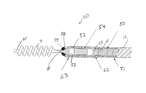
FIG. 16 depicts a plan view of the distal end of
an alternate embodiment of a lead according to the present
invention.
DETAILED DESCRIPTION OF THE INVENTION
FIG. 1 is a schematic view of a lead in use with a
pacing system 2, showing conductors 3, 4 electrically
connected to an implantable pulse generator 5. Implantable
P-2366
6 21~~~~~
pulse generator 5 is constructed from a battery 9, a sense
amp 10, a microprocessor 11, and an output amp 12. Through
such a pacing system 2 the lead of the present invention may
be used to electrically stimulate and sense body tissue, such
as a heart.
FIG. 2 shows a lead 1 according to the present
invention in use as part of a pacing system 2 and implanted
within a heart 13. Lead 1, as seen, has essentially seven
parts or sections: connector 8, lead body 14, pad electrode
15, secondary-lead body 16, sleeve electrode 20, suture 21
and needle 22 (not shown in FIG. 2 but shown in FIG. 4.) As
seen pad electrode 15 is positioned on the surface of heart
13 and sleeve electrode 20 is implanted within the cardiac
tissue, and specifically within myocardium 23.
As seen in FIG. 2 connector pin 8 electrically
connects implantable pulse generator 5 to lead 1, and
specifically to lead body 14. A cross-section of lead body
14 may be seen in FIG. 3. As seen lead body 14 is
constructed from a multi-lumen insulative cover 24 and
conductors 25. Insulative cover 24 is constructed from a
composite of materials, in the preferred embodiment outer
tube 34 is polyurethane and inner tube 35 is polyvinylidene
fluoride. Inner tube 35 provides longitudinal stiffness~to
lead body 14 to prevent it from stretching during
implantation and possible repositioning, as described below.
Although polyvinylidene fluoride is the preferred material
for inner tube 35, other materials which provide a lead body
having sufficient longitudinal stiffness may also be used.
Insulative cover 24 has four lumens 30, 31, 32 and 33, three
of which 30 - 32 each -have a conductor, and the fourth 33
having three conductors. In the preferred embodiment the
three central conductors 25 are electrically connected to pad
electrode 15, while the other conductors are electrically
connected to the sleeve electrode 20. In the preferred
embodiment conductors 25 are a bundled stranded wire. A
suitable bundled stranded wire may be formed from a bundle of
nine wires, each made from a MP35N alloy and having a
diameter of 0.001 inches, the bundle then drawn through a die
to yield a bundle diameter of 0.005 inches. Although in the
7 214~.~3Q
66?42-500
preferred embodiment conductors 25 are bundled stranded wire,
other conductor embodiment may be used, such as, for example,
multifilar wire and coiled conductors.
FIG.4 is a plan view of distal end 40 of lead body 14
showing pad electrode 15 connected thereto. Pad electrode 15
is constructed from pad housing 41 and pan 42, as best seen in
FIG. 5. Pad housing 41 has a pair of fixation wings 46, as
seen in FIGS. 4 and 12. Holes 47 in fixation wings 46 permit
pad electrode 15 to be fixed by sutures to heart. Other
methods of fixing dad electrode l5 to heart may be used
besides sutures, including, for example, fibrin glue, cyano-
acrylate adhesive, staples, or the provision of a polyethylene
terephthalate mesh on the lower surface of pad housing 41. As
seen in FIG. 5, region 49 within pad housing 41 is back filled
with silicone medical adhesive during assembly to fix pan 42 in
place. Pan 42 features a crimp-cover 43 to crimp about
conductors 25 and thereby electrically connect conductors 25 of
lead body 14. Pan 42 is covered by electrode material 70.
Distal end 44 of pad housing 41 features a skirt-portion 45
into which secondary-lead body 14 is attached.
Secondary-lead body 16, as best seen in FIGS. 5 and 6
consists of a secondary-conductor 50 surrounded by a secondary-
insulative cover 51. Secondary-insulative cover 51 is made from
a biocompatible insulative material, preferably polyurethane
although silicone rubber may also be used. Secondary-conductor
50 is a coiled conductor. A coiled conductor is preferred
because this portion of the lead T rides directly upon, and
within, heart 13 and thus is subject to compressive loading
7a
66742-500
during cardiac contraction. Of course it should be understood
that other conductors besides a
P-2366
8 2~~~.~3~
coiled conductor may be provided for secondary-conductor 50
without departing ffom the scope of the present invention.
Secondary-conductor 50 is connected to conductors 25 by
junction 48. Specifically junction 48 is crimped about
conductors 25. Junction 48 is further welded to secondary-
conductor 50. Secondary-conductor 50 is preferably
constructed from a MP35N alloy although a platinum iridium
alloy may also be used.
FIG. 6 is a cross-sectional detail view of the
directional sleeve electrode 20. FIG. 7, 8, 9, 10 and 11
show further details of sleeve electrode 20 and particularly
formed tube 52 used in lead 1 according to the present
invention. As seen sleeve electrode 20 is constructed from
a formed-tube' 52 having a central-cavity 53. As seen in FIG.
6, sleeve electrode 20 has a distal end having a slight taper
38. The use of taper 38 along with the thin cylindrical
shape of formed tube 52 permits sleeve electrode 20 to be
readily inserted into the heart with a minimum of irritation
and damage to the tissue. The precise angle of taper 38 may
vary and still be within the scope and spirit of the present
invention. In addition a small amount of a medical adhesive
39 or any other biocompatible material may be provided at
distal end of sleeve electrode 20 in order to further
increase the streamline shape of sleeve electrode 20. As
discussed above minimizing the trauma of lead insertion, as
well as minimizing the trauma caused by the chronic
implantation of a rigid electrode, is important to thereby
minimize tissue reaction and thus thresholds.
As previously mentioned, sleeve electrode 20
further has located within central-cavity 53, in the
preferred embodiment, a monolithic controlled release device
(MCRD) 54. MCRD 54 is preferably constructed from silicone
rubber and a glucocortico steroid. Formed-tube 52 is
constructed from a biocompatible conductive material, in the
preferred embodiment a platinum-iridium alloy. Distal end of
formed-tube 52 is crimped about proximal end 60 of suture 21.
As seen, proximal end 60 of suture 21 is deformed to increase
its diameter and thereby permitting crimping to accomplish a
joint. Proximal end 56 of formed tube 52 is attached to
CA 02141530 1999-06-30
9
distal end 61 of secondary-conductor 50, preferably by a
series of welds 62. Substantially all of formed tube 52 is
covered by a covering of insulative material 63, such as by
medical adhesive or polyurethane or any other suitable
biocompatible insulative material, except for area 64
proximate holes 65. Area 64 is covered by porous electrode
material 70, as best seen in FIG. 7. Holes 65 in formed-tube
52 allow MCRD 54 to communicate to tissue proximate sleeve
electrode 20. The holes 65 and substantially aligned porous
electrode material 70 serve as a port by means of which the
central cavity or chamber 53 communicates with the exterior of
the insulative covering. Communication between central cavity
53 and the tissue proximate sleeve electrode 20 is important
because it permits use of a steroid or other drug with the
electrode. Specifically sleeve electrode 20 may be configured
to allow the drug to be eluted through or around the electrode
material 70 in order to reduce the acute and chronic
inflammation occasioned by the foreign body response to the
lead and in particular in the region proximate electrode
material 70.
The anti-inflammatory agent, preferably a derivative
of dexamethasone, such as the steroid dexamethasone sodium
phosphate, is loaded in MCRD 54. The steroid also is
deposited within the pores of porous electrode material 70 by
application of a solution of dexamethasone sodium phosphate
dissolved in a mixture of isopropanol and distilled or
deionized water. 'The small geometric electrode size of sleeve
CA 02141530 1999-06-30
9a
electrode 20 is intended to produce very high pacing
impedance. The porous surface of electrode material 70
together with platinum black electroplating contribute to a
microscopically large surface area for low polarization and
relatively low source impedance. The porosity of electrode
material 70 also facilitates the elution of steroid, adhesion
of the platinum black to the electrode surface as well as the
chronic fixation of the electrode 20 to the myocardial tissue.
Electrode material 70 is preferably a porous
platinum composition coated with platinum black. The
porosity, together with the platinum black coating is intended
to reduce source impedance and polarization. Although
platinum is the preferred material for electrode material 70,
it may additionally include or be made entirely
P-2366
to 2141~3~
66742-500
from various other materials, including but not limited to
such materials as palladium, titanium, tantalum, rhodium,
iridium, carbon, vitreous carbon and alloys, oxides and
nitrides of such metals or other conductive materials. Of
course, some materials are incompatible with others and may
not be effectively used together. The limitations of
specific materials for use with others is well known in the
art. Examples of acceptable electrode materials and
associated fabrication techniques employed to achieve the
micro-porous structure may be found in Stokes, U.S. Patent
No. 4,506,680 and related Medtronic U.S. Patent Nos.
4,577,642; 4,606,118 and 4,711,251 and in the Richter et al.,
U.S. Patent No. 4,773,433; Heil Jr. et al., U.S. Patent No.
4,819,661; Thoren et al., U.S. Patent No. 4,149,542; Robblee,
U.S. Patent No. 4,677,989; Heil Jr. et al., U.S. Patent No.
4,819,662; Mund et al., U.S: Patent No. 4,603,704; Skalsky et
al., U.S. Patent No. 4,784,161 and Szilagyi, U. S. Patent
No. 4,784,160. -
As seen sleeve electrode 20 features an electrode
surface in only one direction, i.e. only in the direction of
area 64. A directional electrode has been found beneficial
because it limits the electrical field to be propagated from
the electrode to the specific tissue of interest, e.g. the
myocardium, while concurrently minimizing the exposure of
other tissues, e.g. diaphragm or nerves, to the same
electrical field. In addition, because the electrical field
is more precisely emitted, the active area of the sleeve
electrode 20 may be decreased to thereby achieve a higher
pacing impedance. In addition, this design further permits
the sleeve electrode 20 to be positioned at a point where the
electrode is proximal to desired sections of the myocardium
as well as permitting placement within the epicardium at the
optimal sensing vector. Design of sleeve electrode 20,
moreover, besides permitting directional stimulation and
sensing also permits the incorporation of an MCRD'as well as
presenting an easy to insert profile. In the preferred
embodiment sleeve electrode 20 electrically communicates with
the myocardial tissue in a direction perpendicular to the
longitudinal axis of the lead, as best seen in FIG. 4. Other
P-2366 CA 02141530 1999-06-30
- ' ' 11
directions may, however, be used, such as an electrode which
would electrically cammunicate with the myocardial tissue in
a direction par-allel to the longitudinal axis of the lead.
In fact any specific direction may be used.
Pad electrode 15 has a surface area approximately
ten times (10X) greater than sleeve electrode 20. In the
preferred embodiment pad electrode 15 has a surface area of
12 mm sq. and sleeve electrode 20 has a surface area of 0.8
mm sq.
Implantation of lead 1 is begun by inserting
atraumatic needle 22 through myocardial tissue 23 to it exits
at location 80. As seen in FIG. 13, suture 21 is pulled
until sleeve electrode 20 is properly positioned within part
of channel 81, :in electrical contact with tissue of heart 13.
Suture 21 is preferably ~'PROLENE. Tension is exerted on
coiled section 71 by pulling suture 21 in direction of arrow
86, and the resistive friction between sleeve electrode 20
and heart 13 causes coiled section 71 to stretch and become
temporarily elongated.
While. tension is continuously applied to suture 21
for maintaining coiled section 71 in its extended and
elongated state, suture 21 is severed with a conventional
cutting instrument, such as a pair of scissors to remove
excess portion and dispose of needle 22.
In some applications it may be desirable to sever
suture 21 at a point which includes at least a part of the
coils 71. This will ensure only a selected number of turns
72, 73 and 74, as seen in FIG. 14, are left inside channel
81. The number of turns may be selected by the surgeon,
depending on whether lead 1 is inserted in the atrial or
ventricular wall, and depending on the age or physical
condition of the patient. If lead 1 is used for ventricular
applications, for example, it may be acceptable to leave most,
if not all of ~~urns 72, 73 and 74 within channel 81 of the
myocardium tissue 23. If lead 1 is used for pediatric or
atrial applications, however, then a lesser number of turns
72 and 73 of coiled section 71 might be used to retain lead
1 in place. In order to facilitate the selection process the
lead 1 of the present invention may feature coding along
* Trade-mark
12 ~~~~~30
66742-500
suture 21 as disclosed in U. S. Patent No. 5,217,027 to
Hermens. Special coding along suture 21 may be. accomplished
through a series of color codings or identification marks along
suture 2l to indicate to the surgeon the length to which the
suture 21 must be pulled through myocardium tissue 23 in order
to retain lead in position. In the present illustration shown
in FIG. 15, markings 86, 87 and 88, such as a color coded
indentation, visually indicate to the surgeon the number of
turns 72, 73 and 74 within channel 81.
Once electrode is atisfactorily positioned suture 21
is cut to the desired length and coiled section 71 retracts
towards sleeve electrode 20 within channel 81. Coiled section
71, due to the compressive elasticity of turns 72, 73 and 74,
wedges in the myocardial tissue 23 and thereby firmly affixes
sleeve electrode 20 in tissue 23. If lead 1 is unsatisfactorily
positioned, however, it may be removed by gently retracting it
from channel 81 through traction along lead body 14. Lead 1
may then be reinserted at the next desired site as described
above, assuming, of course that suture 21 and in particular
needle 20 has not been separated.
Once sleeve electrode 20 is positioned, pad electrode
15 is placed flush against the surface of myocardial tissue 23.
If desired pad electrode 15 may be sutured in place through the
use of suture holes 27 and suture 89, although suturing is not
always necessary.
FIG. 16 depicts a plan view of the distal end of an
alternate embodiment of a lead according to the present
211530
12a
66742-500
invention. As seen this embodiment is similar to that
previously described with the exception of having a pair of
secondary-conductors 50a and SOb, each having an electrode.
As seen the sleeve electrode 20 on'secondary-conductor 50a is
similar to that previously described. Electrode 120 on
secondary-conductor 50b is constructed in a similar manner as
sleeve electrode:20 with the exception of not being directional
nor utilizing an MCRD 53. In addition electrode 120 has a
surface area approximately ten times (10X) greater than sleeve
electrode 20, in the preferred embodiment
' ~ P-2366
13
electrode 120 has a surface area of 12 mm sq. and sleeve
electrode 20 has a surface area of 0.8 mm sq.
Installation of this embodiment is the same as
described above, but requiring a pair of sutures 21 to be
inserted. Although not shown, each suture has a needle 20
attached to it.
The present invention may further be incorporated
within a unipolar lead. Such a unipolar embodiment would
differ from the bipolar embodiment through the absence of
either pad electrode 15 or sleeve electrode 20.
While the embodiment of the present invention has
been described in particular applications, it will be
understood the invention may be practiced in other lead and
electrode technologies where the aforementioned
characteristics are desirable, including neurological and
muscle stimulation applications.
Furthermore, although the invention has been
described in detail with particular reference to a preferred
embodiment and alternate embodiments thereof, it will be
understood variations and modifications can be effected
within the scope of the following claims. Such modifications
may include substituting elements or components which perform
substantially the same function in substantially the same way
to achieve substantially the same result for those described
herein.