Note : Les descriptions sont présentées dans la langue officielle dans laquelle elles ont été soumises.
" 2~.46~8~
TRH\SFER DEVICE FOR BEST GLASS SHEETS
The invention concerns a transfer device for bent glass sheets
during the course of automated production of motor vehicle windows
on a production line with continuous furnace for heating the glass
sheets to be bent to bending temperature, bending press with male
bending mould and female bending mould installed in the press
frame, where the male bending mould and/or the female bending mould
can be raised and lowered, in which the heated glass sheets are
bent consecutively in horizontal position in accordance with
specified nominal geometry, toughening station for cooling the
finish-bent glass sheets and a device for onward conveyance of the
cooled glass sheets, where the transfer device operates between
bending press and toughening station.
Production lines of the construction described and of the function
described are known in practice in various configurations. At least
the bending press and the toughening station operate cyclically. In
modern technology, such production lines must meet a number of
basic requirements, that is to say on the one hand operate with
high output and thus short cycle times, on the other hand supply
products such as fnr example bent glass sheets, which maintain
close and extreme tolerances in respect of production accuracy. In
addition, they would have to be able to be set up at short notice
and in a simple manner for different bending geometry if different
glass sheets have to be bent differently in batches and frequently
as well with relatively small batch sizes.
In the case of the known production line to which the transfer
device belongs, on which the invention is based (WO 90/11973), the
transfer device is a shuttle transfer device whose shuttle is
located in the station frame. For this purpose, mounting cross-
beams are provided as shuttle mounting, to which the shuttle is
attached. The mounting cross-beams era movably supported on cross-
beam guides of the station frame and are freely retractable into
the press frame of the bending press. This has proved satisfactory,
but is capable of improvement if short cycle times, high levels of
accuracy in relation to the bent glass sheets are required and in
addition it is be ensured that even with extremely short cycle
~214~~~~
times, deformation faults caused by vibration and resulting from
high forces from positive or negative acceleration do not occur on
the glass sheets.
The invention is based on the technical problem of developing the
configuration of a transfer device for the purpose described above
such that even with extremely short cycle times, glass sheets are
produced with a high degree of precision and free from faults. In
addition, the transfer device should be readily and quickly re-
settable for the~manufacture of different products.
To solve this problem, the subject of the invention is a transfer
device of the configuration described at the beginning, where
combination of the following features is realized:
transfer device for bent glass sheets during the course of
automated production of motor vehicle glass windows on a
production line with
continuous furnace for heating the glass sheets to be bent to
bending temperature,
bending press with male bending mould and female bending mould
installed in the press frame, where the male bending mould
and/or the female bending mould can be raised and lowered, in
which the heated glass sheets are bent consecutively in
horizontal position in accordance with specified nominal
geometry,
toughening station for cooling the finish-bent glass sheets
and
device for onward conveyance of the cooled glass sheets,
where the transfer device operates between bending press and
toughening station and combination of the following features is
realized:
;.
2.~4688~
J
a) the transfer device is a shuttle transfer device whose shuttle
is guided on its aides facing in direction of travel on
shuttle guide rails,
b) the shuttle guide rails are supported statically on the one
hand on the press frame of the bending press and an the other
hand on the station frame of the toughening station as beams
on two supports or as continuous beams,
c) the shuttle incorporates a shuttle frame se well as a shuttle
ring mounted therein and the shuttle frame is guided on the
shuttle guide rails by means of a shuttle frame mounting,
d) the shuttle ring is adjustable in relation to the shuttle
frame mounting and thus in relation to the male bending mould,
e) the shuttle ring incorporates at its edges positioning devices
for the accepted glass sheets,
where at least the areas of the shuttle guide rails which project
into the press frame of the bending press are removable for the
purpose of carrying out maintenance and/or retooling work on the
bending press.
The invention is based on the principle that with a transfer device
which incorporates mounting cross-beams for the shuttle projecting
into the press frame and moved in the manner described, undesirable
vibrations are unavoidable when it is necessary to operate with
high cycle times. Such vibrations do not occur if additional
shuttle guide rails are used which are statically arranged as beams
on two supports or as continuous beams. In addition however exact
positioning of the shuttle ring in relation to the male bending
mould must be ensured and in addition there must be further mea-
sures which so to speak neutralize the acceleration forces which
act on the still soft, bent glass sheets accepted by the shuttle.
All this takes place as a result of combining features a) to e),
where matching to different operating conditions is also possible
without difficulty because at least the areas of the shuttle guide
rail which project into the press frame of the bending press are
2I~~~~9
,.~ _
removable from the bending press for the pur~rose of carrying out
maintenance and retooling operations. As a result, bent glass
sheets are produced which camply with the specified geometry within
very close tolerances and do not incorporate faults resulting from
acceleration forces or vibration.
In detail there are several options for further configuration and
design within the scope of the invention. Usefully, the male
bending mould incorporates a vacuum locating device for retaining
and locating a glass sheet for transfer to the shuttle. For match-
ing to different operating conditions, for example for matching to
female bending moulds of differing geometry, the shuttle guide rail
can be supported on the press frame as well as on the station frame
so se to be vertically adjustable and are there adjustable for
different male bending moulds and differently equipped male bending
moulds. The shuttle frame mounting can be configured in various
ways. It consists preferably of mounting eross-beams traversable or
movable along the shuttle guide rails. The shuttle ring is usefully
attached to the shuttle frame with mounting brackets. In this
respect, it is also possible to realize degrees of freedom of
adjustment. To equip the shuttle frame and thus the shuttle ring,
it is sufficient in the si.~nplest instance for the shuttle frame to
be attached to the shuttle frame mounting in direction of travel,
on the one hand rigidly and on the other hand adjustably. This can
be done for examgle with adjustable screw fastenings. The position-
ing devices preferably taking the form of positioning clamping
devices do not according to experience lead to undesirable marks on
the still soft glass sheets if they act on the cut edge faces of
the bent glass sheets. For this purpose, the positioning clamping
devices can incorporate rotary cylinders and clamping levers or
clamping cams which act against the cut edge faces of the glass
sheets.
In the case of the transfer device according to the invention, the
shuttle guide rails can take the farm of rigid rails and can be
extendable horizontally from the press frame and also retractable
again into the press frame. This extension and retraction is
realized if the bending press has to be retooled for any reason,
for example for the purpose of changing the male bending mould and
21~~88~
female bending mould. For this purpose, it is also possible for the
shuttle guide rails to incorporate a folding joint and that the
areas of shuttle guide rails projecting into the press frame can be
folded out of it. The shuttle ring usefully takes the form of a
rigid component. This means that in the event of modifications of
the bending geometry, the shuttle ring will have to be changed. In
the case of the embodiment according to the invention, this is
possible without difficulty.
If a transfer device according to the invention is installed and
integrated in the automated production of motor vehicle glass
windows in a production line, control of the various components of
the transfer device according to the invention is effected with the
equipment of modern drive and control engineering without diffi-
culty. particularly as well with computer control of the entire
production range.
The invention is explained in detail with the aid of a drawing
illustrating only one embodiment. It shows the following:
Fig. 1: the side elevation of a transfer device according to the
invention,
Fig. 2: a perspective view on a significantly larger scale than
Fig. 1, the shuttle frame with shuttle ring from the
subject of Fig. 1,
Fig. 3: on a larger scale that Fig. 2, the shuttle ring from the
subject of Fig. 2 and
Fig. 4: in a plan view of the subject according to Fig. 3,
details of a positioning device in the form of a posi-
tioning clamping device on the shuttle ring of Fig. 3,
Fig. 5s the subject of Fig. 4 in a different functional position.
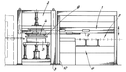
The transfer device 1 for bent glass sheets illustrated in the
Figures is intended for automated production of motor vehicle glass
windows. The production line as a whole has not been illustrated.
_21~688~
6
In this respect, to avoid repetition, reference is made to the
state of the art described at the beginning (WO 90/11973). In Fig.
1 one can recognize the bending press 2 With the press frame 3,
raisable and lowerable male bending mould 4 and raisable and
lowerable female banding mould 5, where in this bending press 2,
the glass sheets previously heated in a continuous furnace are bent
consecutively in a horizontal position in accordance with specified
nominal geometry. On the right is adjoined a toughening station 6
for toughening the finish-bent glass sheets, which in turn operated
on a device 7 foi onward conveyance of the toughened glass sheets.
The transfer device 1 operated between bending press 2 and toughen-
ing station 6.
The transfer device 1 is a shuttle transfer device whose shuttle 8
is guided along its sides in direction of ccnveyance along shuttle
guide rails 9. The shuttle guide rails 9 are supported on the one
hand on the press framQ 3 of the bending press 2, and on the other
hand on the station frame 10 statically as beams on two supports or
as continuous beam.
From comparative consideration of Figs. 2 and 3, it can be seen
that the shuttle 8 incorporates a shuttle frame 11 and a shuttle
ring 12 supported in it. The shuttle frame 11 is guided, by means
of a shuttle frame mounting 13 traversable along the shuttle guide
rails 9, along the shuttle guide rails 9. The shuttle ring 12 is
adjustable in relation the shuttle frame mounting 13 and thus in
relation to the male bending mould 4. The shuttle ring 12 incorpo-
rates at its edges automatically operable positioning clamping
devices 14 for the accepted glass sheets. At least the areas of the
shuttle guide rails 9 which project into the press frame 3 of the
bending press 2 are removable for the purpose of carrying out
maintenance and/or retooling operations on the bending press 2.
1n Fig. 1, arrows indicate that the shuttls guide rails 9 are
supported on the press frame 3 as well as on the station frame 10
so as to be vertically adjustable. They are thus adjustable for
different female bending moulds 5 and variously installed male
bending moulds 4. In the example and according to a preferred
embodiment of the invention, the shuttle frame mounting 13 is
_214~88~
constructed from the mounting cross-beams 16 traversable along the
shuttle guide rails 9. By traversable is meant an embodiment where
rollers are not used, but slide-like traversing takes place.
From Figa. 2 and 3 it can also be seen that the shuttle ring 12 is
attached with mounting brackets 17 to the shuttle frame 11. These
mounting brackets 17 for their part are adjuetable,.which is not
shown.
The shuttle frame 11 ie fixed on one side and on the other side
adjustably attached to the shuttle frame mountings 13. Adjustment
can be effected by means o.f corresponding positioning gear units,
cams or the like.
From comparative consideration of Figa. 3 to 5, it can be seen that
the positioning clamping devices 14 act on the cut edge faces 18 of
the glass sheets 19. In the example, the goeitioning clamping
devices are rotary cylinders with clamping lever or cams 20. Of
course, they permit remote control.
Fig. 1 indicates that the shuttle guide rails 9 take the form of
rigid rails. They are retractable and extendable horizontally into
the preaa frame 3 and as illustrated can be supported in the
station frame 10. The shuttle guide rails 9 can also however
incorporate a folding joint and areas of the shuttle guide rails
projecting into the press frame 3 could be folded out of the press
frame 3. The shuttle ring 12 takes the form of a rigid component;
it must be changed when bending of different glass sheets is
involved which are to be bent in accordance with different nominal
geometry. - Alignment and adjustment of the shuttle ring 12,
matching it to the male bending mould 4, can be carried out simply
and with great accuracy with the use of an auxiliary device.