Sélection de la langue

Search

Sommaire du brevet 2147196 

Énoncé de désistement de responsabilité concernant l'information provenant de tiers

Une partie des informations de ce site Web a été fournie par des sources externes. Le gouvernement du Canada n'assume aucune responsabilité concernant la précision, l'actualité ou la fiabilité des informations fournies par les sources externes. Les utilisateurs qui désirent employer cette information devraient consulter directement la source des informations. Le contenu fourni par les sources externes n'est pas assujetti aux exigences sur les langues officielles, la protection des renseignements personnels et l'accessibilité.

Disponibilité de l'Abrégé et des Revendications

L'apparition de différences dans le texte et l'image des Revendications et de l'Abrégé dépend du moment auquel le document est publié. Les textes des Revendications et de l'Abrégé sont affichés :

  • lorsque la demande peut être examinée par le public;
  • lorsque le brevet est émis (délivrance).
(12) Brevet: (11) CA 2147196
(54) Titre français: DETECTEUR HYPERFREQUENCE ACCORDE
(54) Titre anglais: MICROWAVE INTEGRATED TUNED DETECTOR
Statut: Périmé et au-delà du délai pour l’annulation
Données bibliographiques
(51) Classification internationale des brevets (CIB):
  • G01R 21/01 (2006.01)
  • G01R 21/12 (2006.01)
  • H01Q 09/04 (2006.01)
  • H01Q 23/00 (2006.01)
(72) Inventeurs :
  • OPREA, ALEXANDRU (Canada)
(73) Titulaires :
  • KASTEN CHASE APPLIED RESEARCH LIMITED
(71) Demandeurs :
  • KASTEN CHASE APPLIED RESEARCH LIMITED (Canada)
(74) Agent: MARKS & CLERK
(74) Co-agent:
(45) Délivré: 2002-11-19
(22) Date de dépôt: 1995-04-18
(41) Mise à la disponibilité du public: 1995-11-10
Requête d'examen: 2002-03-19
Licence disponible: S.O.
Cédé au domaine public: S.O.
(25) Langue des documents déposés: Anglais

Traité de coopération en matière de brevets (PCT): Non

(30) Données de priorité de la demande:
Numéro de la demande Pays / territoire Date
08/239,454 (Etats-Unis d'Amérique) 1994-05-09

Abrégés

Abrégé anglais


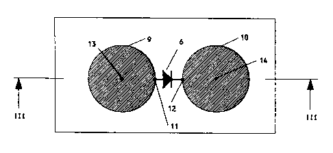
A microwave detector, which integrates two circular
patch antennas with a detector diode. The high impedance
at the edge of the circular patch antenna is combined
with 180° out of phase electric fields at diametrically
opposite points, so as to match to the RF impedance of a
zero or small DC bias diode. The result is a very
simple, high-sensitivity narrow-band microwave integrated
detector.

Revendications

Note : Les revendications sont présentées dans la langue officielle dans laquelle elles ont été soumises.


5
I CLAIM
1. A microwave integrated tuned detector for
receiving microwave signals in a predetermined frequency
range, comprising:
a) a DC output;
b) a substrate;
c) a grounded plane mounted on one side of said
substrate;
d) at least two circular patch antennae mounted
on an opposite side of said substrate from said grounded
plane, said antennae being of predetermined radius for
exciting a dominant TM11 mode in said predetermined
frequency range;
e) a detector diode having one terminal thereof
connected to one of said at least two circular patch
antennae, and having an opposite terminal thereof
connected to the other of said at least two circular
patch antennae;
f) a centre point of said one of said at least
two circular patch antennae being connected to said
grounded plane for providing a DC return path for said
detector diode; and
g) a centre point of said other one of said at
least two circular patch antennae being connected to said
DC output.
2. The microwave integrated tuned detector of
claim 1, wherein said detector diode is a Schottky diode.
3. The microwave integrated tuned detector of
claim 2, wherein said Schottky diode is unbiased.
4. The microwave integrated tuned detector of
claim 2, wherein said Schottky diode is biased at a small
DC current.

6
5. The microwave integrated tuned detector of
claim 1, wherein said detector diode is connected to
respective edges of said at least two circular patch
antennae.

Description

Note : Les descriptions sont présentées dans la langue officielle dans laquelle elles ont été soumises.


214719~
MICROWAVE INTEGRATED TUNED DETECTOR
Field of the Invention
This invention relates in general to microwave tuned
detector-receivers, and more particularly to a low-cost,
high-sensitivity microwave tuned receiver which
integrates at least two circular patch ant~nnAs with a
detector diode.
Background of the Invention
Traditional microwave detector designs use resistive
terminations to match an RF source. However, the
detector diodes used in such designs, when operated
unbiased or at a small DC bias, have a relatively high RF
resistance and receive only a small fraction of the
available signal power when connected in parallel to the
resistive termination (e.g. a 50 ohm resistor).
In narrow band applications, high sensitivity tuned
detectors are preferred. Impedance transformation and
reverse-phasing of the detector diode terminals have been
used to increase the sensitivity and output voltage of
the resistive termination used in such prior art designs.
Nevertheless, both ter-hniques have deficiencies. The
first technique makes use of circuit elements such as
quarter-wave high impedance transmission lines, which are
difficult to achieve with conventional lines. The second
ter~;gue requires a 180 power divider. The requirement
for additional elements to implement these two prior art
tec~nique~ increases the complexity and size of the
detector assembly and introduces extra losses.
Summarv of the Invention
In accordance with the present invention, two
closely separated circular patch antennae are provided
for receiving the microwave signal. A detector diode is
placed in between the two antennae and is connected to
their respective adjacent edges. The centre of one
antenna is grounded to provide the DC return path for the
diode. The centre of the second antenna provides the DC

2l ~7196
output of the detector.
The integrated tuned detector embodying the present
invention takes advantage of both prior art techniques
without requiring the use of additional elements. The
re~ult is a very simple, high-sensitivity integrated
tuned detector.
The detector of the present invention has the
following improvemQnts over prior art tuned detectors:
(1) It combines the input power from two antennae
resulting in a 6dB increase in output voltage.
(2) It provides a certain degree (dep~ ng on antenna
separation) of spatial diversity;
(3) It doe~ not need circuit elements to filter out the
high frequency component at the output of the detector;
(4) It doe~ not need circuit elements to provide a DC
path for the diode.
Further advances of the microwave detector embodying
the invention will be more fully understood from a
consideration of the following detailed description in
conjunction with the accompanying drawings.
Brief Descri~tion of the Drawinqs
In the drawings:
Figure 1 i~ an equivalent functional diagram of a
high-sensitivity integrated tuned detector according to
well known design;
Figure 2 shows an implementation on microstrip of an
integrated tuned detector according to the present
invention;
Figure 3 i~ a cross-section through the lines III-
III in Figure 2; and
Figure 4 shows an alternative embodiment in which
circuitry for performing polarization diversity has been
added.
Detailed Descri~tion of the Preferred Embodiment
Figure 1 shows the equivalent functional diagram of
a high-sensitivity integrated detector. The antenna 1
receives the microwave signal. The power spliter 2

214719fi
divides the input power evenly and applies it to the
impe~co transformers 3 and 5, with a 180 phase
difference. The impedance transformer 3 raises the
impedance to as high a value as is practical and feeds
the anode of a Schottky barrier detector diode 6. The
impe~nss transformer 5 provides the same function as the
impedance transformer 3 and supplies the cathode of the
diode 6. The high freguency component of the detected
signal is removed by low-pass filter 7. The inductor 4
provides the DC return path for the diode 6.
These functions may be implemented very simply
through the exploitation of well known patch antenna
teçhnology.
Figures 2 and 3 show an implementation on microstrip
of these functional blocks according to the present
invention.
A pair of circular patch antennae 9 and 10 are
disposed on a substrate 15, having a ground plane 16 on
the opposite side from the antenna patches 9 and 10. The
radius of both circular patch antennae 9 and 10 is
calculated to excite the dominant TM~1 mode at any
frequency of intQrest. For this mode, the electrical
field is zero at the centre of the patch. However, at
diametrically opposite points on the circumference of the
patch the electric fields are 180 out of phase. In
addition, the impedance at the edge of each patch is very
high (i.e. hundreds of ohms.). Further exploiting this
knowledge, it is clear that the signals at points 11 and
12 are 180 out of phase (functional block 2 in Figure 1).
Furthermore, because of the high impedance at points 11
and 12, impedance transformation (functional blocks 3 and
5 in Figure 1) is performed by the antennae themselves.
The electrical field is zero at the centre point 13
of the antenna 9 and therefore it can be grounded to
provide the DC return path for the diode 6 (the function
of the inductor 4 in Figure 1).
The DC output ~ignal i~ present at point 14.

2147191~
Because the field is zero at this point as well, low-pass
filtration (block 7 in Figure 1) is performed by antenna
10. The DC return point 13 and DC output point 14 can be
interchanged, thereby producing a DC output with reverse
polarity.
Accordingly, the configuration of the present
invention results in a high-sensitivity integrated tuned
detector utilizing only three elements.
Alternative variations are possible. In Figure 4 an
example of an integrated tuned detector i8 shown with
polarization diversity. The configuration is essentially
a combination of two orthogonal integrated tuned
detectors in accordance with the present invention (i.e.
by including an additional circular patch antenna 18 with
grounded centre 19, and connected to antenna 10 via an
additional diode 17). The two detectors of Figure 4
share the antenna 10, which also act~ as diversity
combiner.
All ~uch alternative variations are believed to be
within the sphere and scope of the present invention as
defined by the claims appended hereto.

Dessin représentatif
Une figure unique qui représente un dessin illustrant l'invention.
États administratifs

2024-08-01 : Dans le cadre de la transition vers les Brevets de nouvelle génération (BNG), la base de données sur les brevets canadiens (BDBC) contient désormais un Historique d'événement plus détaillé, qui reproduit le Journal des événements de notre nouvelle solution interne.

Veuillez noter que les événements débutant par « Inactive : » se réfèrent à des événements qui ne sont plus utilisés dans notre nouvelle solution interne.

Pour une meilleure compréhension de l'état de la demande ou brevet qui figure sur cette page, la rubrique Mise en garde , et les descriptions de Brevet , Historique d'événement , Taxes périodiques et Historique des paiements devraient être consultées.

Historique d'événement

Description Date
Le délai pour l'annulation est expiré 2008-04-18
Inactive : Demande ad hoc documentée 2007-06-13
Lettre envoyée 2007-04-18
Inactive : CIB de MCD 2006-03-11
Accordé par délivrance 2002-11-19
Inactive : Page couverture publiée 2002-11-18
Inactive : Taxe finale reçue 2002-09-05
Préoctroi 2002-09-05
Lettre envoyée 2002-05-23
Un avis d'acceptation est envoyé 2002-05-23
Inactive : Approuvée aux fins d'acceptation (AFA) 2002-05-15
Lettre envoyée 2002-04-15
Inactive : Renseign. sur l'état - Complets dès date d'ent. journ. 2002-04-15
Inactive : Dem. traitée sur TS dès date d'ent. journal 2002-04-15
Toutes les exigences pour l'examen - jugée conforme 2002-03-19
Exigences pour une requête d'examen - jugée conforme 2002-03-19
Demande publiée (accessible au public) 1995-11-10

Historique d'abandonnement

Il n'y a pas d'historique d'abandonnement

Taxes périodiques

Le dernier paiement a été reçu le 2002-02-14

Avis : Si le paiement en totalité n'a pas été reçu au plus tard à la date indiquée, une taxe supplémentaire peut être imposée, soit une des taxes suivantes :

  • taxe de rétablissement ;
  • taxe pour paiement en souffrance ; ou
  • taxe additionnelle pour le renversement d'une péremption réputée.

Les taxes sur les brevets sont ajustées au 1er janvier de chaque année. Les montants ci-dessus sont les montants actuels s'ils sont reçus au plus tard le 31 décembre de l'année en cours.
Veuillez vous référer à la page web des taxes sur les brevets de l'OPIC pour voir tous les montants actuels des taxes.

Historique des taxes

Type de taxes Anniversaire Échéance Date payée
TM (demande, 3e anniv.) - générale 03 1998-04-20 1998-02-19
TM (demande, 4e anniv.) - générale 04 1999-04-19 1999-03-08
TM (demande, 5e anniv.) - générale 05 2000-04-18 2000-03-28
TM (demande, 6e anniv.) - générale 06 2001-04-18 2001-03-30
TM (demande, 7e anniv.) - générale 07 2002-04-18 2002-02-14
Requête d'examen - générale 2002-03-19
Taxe finale - générale 2002-09-05
TM (brevet, 8e anniv.) - générale 2003-04-22 2003-04-22
TM (brevet, 9e anniv.) - générale 2004-04-19 2004-04-15
TM (brevet, 10e anniv.) - générale 2005-04-18 2005-03-30
TM (brevet, 11e anniv.) - générale 2006-04-18 2006-04-04
Titulaires au dossier

Les titulaires actuels et antérieures au dossier sont affichés en ordre alphabétique.

Titulaires actuels au dossier
KASTEN CHASE APPLIED RESEARCH LIMITED
Titulaires antérieures au dossier
ALEXANDRU OPREA
Les propriétaires antérieurs qui ne figurent pas dans la liste des « Propriétaires au dossier » apparaîtront dans d'autres documents au dossier.
Documents

Pour visionner les fichiers sélectionnés, entrer le code reCAPTCHA :


Pour visualiser une image, cliquer sur un lien dans la colonne description du document. Pour télécharger l'image (les images), cliquer l'une ou plusieurs cases à cocher dans la première colonne et ensuite cliquer sur le bouton "Télécharger sélection en format PDF (archive Zip)" ou le bouton "Télécharger sélection (en un fichier PDF fusionné)".

Liste des documents de brevet publiés et non publiés sur la BDBC .

Si vous avez des difficultés à accéder au contenu, veuillez communiquer avec le Centre de services à la clientèle au 1-866-997-1936, ou envoyer un courriel au Centre de service à la clientèle de l'OPIC.


Description du
Document 
Date
(aaaa-mm-jj) 
Nombre de pages   Taille de l'image (Ko) 
Abrégé 1995-04-17 1 12
Dessins 1995-04-17 2 61
Description 1995-04-17 4 162
Revendications 1995-04-17 2 41
Dessin représentatif 1998-06-17 1 16
Dessin représentatif 2002-05-15 1 21
Rappel - requête d'examen 2001-12-18 1 118
Accusé de réception de la requête d'examen 2002-04-14 1 180
Avis du commissaire - Demande jugée acceptable 2002-05-22 1 165
Avis concernant la taxe de maintien 2007-05-29 1 173
Taxes 2003-04-21 1 50
Correspondance 2002-09-04 1 51
Taxes 2002-02-13 1 62
Taxes 2000-03-27 1 51
Taxes 2001-03-29 1 50
Taxes 2004-04-14 1 51
Taxes 2005-03-29 1 53
Taxes 2006-04-03 1 54
Taxes 2007-06-20 2 204
Taxes 1997-03-20 1 56
Taxes 1997-04-29 2 68