Sélection de la langue

Search

Sommaire du brevet 2147970 

Énoncé de désistement de responsabilité concernant l'information provenant de tiers

Une partie des informations de ce site Web a été fournie par des sources externes. Le gouvernement du Canada n'assume aucune responsabilité concernant la précision, l'actualité ou la fiabilité des informations fournies par les sources externes. Les utilisateurs qui désirent employer cette information devraient consulter directement la source des informations. Le contenu fourni par les sources externes n'est pas assujetti aux exigences sur les langues officielles, la protection des renseignements personnels et l'accessibilité.

Disponibilité de l'Abrégé et des Revendications

L'apparition de différences dans le texte et l'image des Revendications et de l'Abrégé dépend du moment auquel le document est publié. Les textes des Revendications et de l'Abrégé sont affichés :

  • lorsque la demande peut être examinée par le public;
  • lorsque le brevet est émis (délivrance).
(12) Brevet: (11) CA 2147970
(54) Titre français: DISPOSITIF DE FIXATION INTEGRE A UN IMPLANT DENTAIRE
(54) Titre anglais: FIXTURE IN A DENTAL IMPLANT SYSTEM
Statut: Durée expirée - au-delà du délai suivant l'octroi
Données bibliographiques
(51) Classification internationale des brevets (CIB):
  • A61C 08/00 (2006.01)
  • A61F 02/30 (2006.01)
(72) Inventeurs :
  • HANSSON, STIG GUSTAV VILHELM (Suède)
  • HOLMEN, ANDERS (Suède)
(73) Titulaires :
  • ASTRA AKTIEBOLAG
(71) Demandeurs :
  • ASTRA AKTIEBOLAG (Suède)
(74) Agent: SMART & BIGGAR LP
(74) Co-agent:
(45) Délivré: 2004-08-03
(86) Date de dépôt PCT: 1993-10-25
(87) Mise à la disponibilité du public: 1994-05-11
Requête d'examen: 2000-10-04
Licence disponible: S.O.
Cédé au domaine public: S.O.
(25) Langue des documents déposés: Anglais

Traité de coopération en matière de brevets (PCT): Oui
(86) Numéro de la demande PCT: PCT/SE1993/000871
(87) Numéro de publication internationale PCT: SE1993000871
(85) Entrée nationale: 1995-04-26

(30) Données de priorité de la demande:
Numéro de la demande Pays / territoire Date
9203184-8 (Suède) 1992-10-28

Abrégés

Abrégé anglais


The invention relates to a fixture (1, 10) in a dental implant system having
an outer end provided with a conically flaring
portion (10) intended to at least partly abut the bone tissue. The outer side
of the conically flaring portion (10) is provided with a
circumferentially oriented, defined micro-roughness (9) having a height which
may vary between 0.02 and 0.20 mm.

Revendications

Note : Les revendications sont présentées dans la langue officielle dans laquelle elles ont été soumises.


6
CLAIMS:
1. Fixture (1, 10) of a dental implant system for
implantation in bone tissue having a generally cylindrical
main body provided with threads allowing the fixture to
function as a screw, and an outer end provided with a
conically flaring portion (10) which is intended to at least
partly abut the bone tissue when the fixture is implanted,
characterized in that the outer side of the conically
flaring portion is provided with a circumferentially
oriented, defined micro-roughness (9) having a height in the
range of 0.02 - 0.20 mm.
2. Fixture according to claim 1, characterized in
that said micro-roughness has a height between 0.02 and
0.15 mm.
3. Fixture according to claim 2, characterized in
that said micro-roughness has a height between 0.05 and
0.15 mm.
4. Fixture according to any one of claims 2 or 3,
characterized in that said micro-roughness has a height of
0.1 mm.
5. Fixture according to claim 1, characterized in
that the defined micro-roughness is in the form of
circumferential beads.
6. Fixture according to claim 1, characterized in
that the defined micro-roughness is in the form of a
microthread (9).
7. Fixture according to claim 5 or 6, characterized
in that the distance between adjacent threads or beads,
crest to crest, is twice the height of the threads or beads.

Description

Note : Les descriptions sont présentées dans la langue officielle dans laquelle elles ont été soumises.

CA 02147970 2003-10-08
28371-31
1
Fixture in a dental implant system.
The present invention relates to fixtures for
dental implants, i.e. the parts of dental implant systems
which are to be implanted in the bone tissue, and
S particularly to fixtures whose outer end or neck are
provided with a sonically flaring portion intended to at
least partly abut the bone tissue.
Background to the invention
Fixtures having a cylindrical main body and a
sonically flaring upper portion or neck have been known and
used in the art of dental implants for a long period of
time. These fixtures are to be inserted into bore-holes in
the jaw-bone in order to become osseointegrated to the bone
tissue. The cylindrical parts generally osseointegrate
correctly provided the proper techniques are used.
There are however some difficulties regarding the
osseointegration around the conical neck portion of the
implants which portion normally is smooth or polished. For
some reason the bone tissue may degenerate around a smooth
or polished conical part (bone resorbtion), leaving a pocket
in the bone tissue around the conical part. The mechanism
behind this is not quite clear. These pockets normally are
accepted as inevitable although it is not entirely
satisfactory that not the entire implant is osseointegrated,
particularly since this pocket is formed in the strongest
part of the bone tissue, the cortical bone.
Short description of the inventive concept
According to the present invention there is
provided fixture (1, 10) of a dental implant system for
implantation in bone tissue having a generally cylindrical

CA 02147970 2003-10-08
28371-31
la
main body provided with threads allowing the fixture to
function as a screw, and an outer end provided with a
sonically flaring portion (10) which is intended to at least
partly abut the bone tissue when the fixture is implanted,
characterized in that the outer side of the sonically
flaring portion is provided with a circumferentially
oriented, defined micro-roughness (9) having a height in the
range of 0.02 - 0.20 mm.
It surprisingly has been found that the provision
of a circumferentially or tangentially oriented, defined
micro-roughness on the outer side of the sonically flaring
portion of the fixture having a height which

t~~ 94/09717 PCT/SE93/00~71
~.~ 9~ ~ ~
may vary between 0.02 and 0.20 mm alleviates this
problem, the risk for pockets in the bone tissue around
the comically flaring portion being minimised.
In preferred embodiments the micro-roughness, as set
forth in the appended dependent claims, may be in the
form of circumferential beads or microthreads.
sh~rt description of the appended drawings
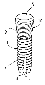
Fig 1 shows the exterior of a fixture according to the
invention,
Fig 2 shows the fixture in fig 1, partly sectioned.
~stailed descript ,~n of s pseferred ~s~ab~d~tent of tb~
indention
Ln the description below, the invention is illustrated
by means of micro-threads. It should be noted that the
description in the relevant parts (i. a. the parts not
relating directly to the helical nature of the threads)
'' also is applicable to the embodiment featuring the
circumferent.ial beads and that this choice does not
ref lect any preference regarding the two embodiments.
Thus, in a preferred embodiment, the invention
comprises an implant or fixture having a generally
cyli;ndricaZ. k~ody 1 ,;fQr insertion into. a bore--hole into
3p bone tissue. The envelope surface of the body l is
provided with conventional threads 2. These threads
will allow the implant to function as a screw. The
forward end or the tip of the screw is provided with
three cutting edges 4 together with chip-collecting
cavities 3.

~~~:~~~~i
9V~ 94109717 PC~'/SE93/~0$71
3
The cutting edges 4 and the chip-collecting cavities 3
will allow the screw, if necessary, to function as a
self--tapping screw for cutting new threads or adjusting
already cut threads in the tissue.
The other end of the screw is, as is quite conventional
in the art, provided with a longitudinal bore for the
attachment of an abutment for bridging the soft tissue
covering the bane tissue and for the attachment of a
l0 prosthesis. The inner part 7 of the bore is cylindrical
and provided with interior threads 6 and the outer part
5 of the bore, which is located in a comically flaring
portion l0) is comically flaring in order to
accommodate a comically tapering attachment part of an
abutment. The transitional portion between the conical
part and the cylindrical bore comprises a hexagonal
docket ~ which is intended to cooperate with a
corresponding, hexagonal part of the abutment in order
to allow the abutment to be oriented and locked in
specific rotational positions relative to the f uture.
As aan be seen in Figs ~, and 2, the outer side of the
cc~nically flaring portion l0 is provided with threads
serving as oriented micro-rotaghness. The threads may be
0. 3- mm laigla and the distance to the sdjacerrt thread
(crest to ~restj may be 0:2 mm. The threads ire here
called microthreads (and the beads microbeads) since
their hoight and distance from each other are in the
micrometer range..The;,~icrothre~ds maybe multiple-,
;., ;~ ..
~
which means that
threaded, for instance triple-threaded
the pitch of the thread would be 0.6 mm. The amgle
between ' the f lanky of a microthread may for instance be
45 or ~0: The micro~threads have a rounded design in
order to avoid; or at least minimize, stress-
concentrations in the bone tissue around the micro-
threads:

f
~V~ 94/09717 ~ ~~'~ ~fw ~~ PCT/SE93/00871
_)
4
Generally, the height of the microthreads may be within
the range of 0.02 - 0.20 mm. In a preferred embodiment
the height may vary between 0.02 and 0.15 mm, in a more
preferred embodiment between 0.05 and 0.15 and in a
most preferred embodiment, described above, the height
is 0.1 mm. The number of threads is optional but may '
for instance vary between 1 and 5.
The microthreads can be regarded as a defined, oriented
roughness being in the same size range as the kind of
prior art non-oriented surface roughness, which for
instance may be obtained by plasma-spraying (a
conventional technique for obtaining a surface
roughness ran implants). A non-oriented roughness having
smaller dimensions, for instance obtained by blasting,
may be superimposed on the micrc~threads.
New bone tissue will rapidly grow a.nto the microthreads
due to the low height of the threads and a retention
which is considerably better in the axial direction
than in the rotational (tangential) direction will be
obtained relatively fast. This of course is a result of
the threads being oriented circumferentially.
It would seem that the gaositive results obtained by
this design may be explained as follows:
When the bone tissue has grown into the spaces between
individual p~ojecti,ans ;of the micro-roughness,, the ,
axial loads on the implant may be transmitted in an
axial direction (related to the axial direction of the
fixture) to the bone tissue around the conical portion
in a biomechanically correct way, i. e. in such a way
that the bone tissue is stressed correctly around the
conical part and that bone resorbtion consequently does
not occur.

CVO 94/0971? ~ ~ ~ ~ ~ xj ~ PCT/SE93/00871
above, the fixture has been described as having normal
threads on the cylindrical main body. It may however be
particularly advantageous if both the main body and the
comically flaring part is provided with microthreads,
;.,
5 since this will allow the fixture to be used both as a
fixture which gently can be tapped or pushed into the
bore-hole and as a fixture which easily can be screwed
into, or unscrewed from, the bore-hole.
It should be emphasized that the invention is not
limited to the emibodiments described above and can be
varied in many ways within the scope of the appended
claims.

Dessin représentatif
Une figure unique qui représente un dessin illustrant l'invention.
États administratifs

2024-08-01 : Dans le cadre de la transition vers les Brevets de nouvelle génération (BNG), la base de données sur les brevets canadiens (BDBC) contient désormais un Historique d'événement plus détaillé, qui reproduit le Journal des événements de notre nouvelle solution interne.

Veuillez noter que les événements débutant par « Inactive : » se réfèrent à des événements qui ne sont plus utilisés dans notre nouvelle solution interne.

Pour une meilleure compréhension de l'état de la demande ou brevet qui figure sur cette page, la rubrique Mise en garde , et les descriptions de Brevet , Historique d'événement , Taxes périodiques et Historique des paiements devraient être consultées.

Historique d'événement

Description Date
Inactive : Périmé (brevet - nouvelle loi) 2013-10-25
Inactive : CIB de MCD 2006-03-11
Accordé par délivrance 2004-08-03
Inactive : Page couverture publiée 2004-08-02
Inactive : Taxe finale reçue 2004-05-18
Préoctroi 2004-05-18
Un avis d'acceptation est envoyé 2004-04-28
Lettre envoyée 2004-04-28
Un avis d'acceptation est envoyé 2004-04-28
Inactive : Approuvée aux fins d'acceptation (AFA) 2004-04-16
Modification reçue - modification volontaire 2003-10-08
Inactive : Dem. de l'examinateur par.30(2) Règles 2003-04-10
Modification reçue - modification volontaire 2000-11-01
Inactive : Dem. traitée sur TS dès date d'ent. journal 2000-10-25
Lettre envoyée 2000-10-25
Inactive : Renseign. sur l'état - Complets dès date d'ent. journ. 2000-10-25
Toutes les exigences pour l'examen - jugée conforme 2000-10-04
Exigences pour une requête d'examen - jugée conforme 2000-10-04
Demande publiée (accessible au public) 1994-05-11

Historique d'abandonnement

Il n'y a pas d'historique d'abandonnement

Taxes périodiques

Le dernier paiement a été reçu le 2003-10-02

Avis : Si le paiement en totalité n'a pas été reçu au plus tard à la date indiquée, une taxe supplémentaire peut être imposée, soit une des taxes suivantes :

  • taxe de rétablissement ;
  • taxe pour paiement en souffrance ; ou
  • taxe additionnelle pour le renversement d'une péremption réputée.

Les taxes sur les brevets sont ajustées au 1er janvier de chaque année. Les montants ci-dessus sont les montants actuels s'ils sont reçus au plus tard le 31 décembre de l'année en cours.
Veuillez vous référer à la page web des taxes sur les brevets de l'OPIC pour voir tous les montants actuels des taxes.

Historique des taxes

Type de taxes Anniversaire Échéance Date payée
TM (demande, 4e anniv.) - générale 04 1997-10-27 1997-09-17
TM (demande, 5e anniv.) - générale 05 1998-10-26 1998-09-23
TM (demande, 6e anniv.) - générale 06 1999-10-25 1999-09-16
TM (demande, 7e anniv.) - générale 07 2000-10-25 2000-10-04
Requête d'examen - générale 2000-10-04
TM (demande, 8e anniv.) - générale 08 2001-10-25 2001-10-02
TM (demande, 9e anniv.) - générale 09 2002-10-25 2002-09-30
TM (demande, 10e anniv.) - générale 10 2003-10-27 2003-10-02
Taxe finale - générale 2004-05-18
TM (brevet, 11e anniv.) - générale 2004-10-25 2004-09-24
TM (brevet, 12e anniv.) - générale 2005-10-25 2005-09-23
TM (brevet, 13e anniv.) - générale 2006-10-25 2006-10-04
TM (brevet, 14e anniv.) - générale 2007-10-25 2007-10-03
TM (brevet, 15e anniv.) - générale 2008-10-27 2008-10-03
TM (brevet, 16e anniv.) - générale 2009-10-26 2009-09-29
TM (brevet, 17e anniv.) - générale 2010-10-25 2010-10-05
TM (brevet, 18e anniv.) - générale 2011-10-25 2011-10-19
TM (brevet, 19e anniv.) - générale 2012-10-25 2012-10-09
Titulaires au dossier

Les titulaires actuels et antérieures au dossier sont affichés en ordre alphabétique.

Titulaires actuels au dossier
ASTRA AKTIEBOLAG
Titulaires antérieures au dossier
ANDERS HOLMEN
STIG GUSTAV VILHELM HANSSON
Les propriétaires antérieurs qui ne figurent pas dans la liste des « Propriétaires au dossier » apparaîtront dans d'autres documents au dossier.
Documents

Pour visionner les fichiers sélectionnés, entrer le code reCAPTCHA :


Pour visualiser une image, cliquer sur un lien dans la colonne description du document. Pour télécharger l'image (les images), cliquer l'une ou plusieurs cases à cocher dans la première colonne et ensuite cliquer sur le bouton "Télécharger sélection en format PDF (archive Zip)" ou le bouton "Télécharger sélection (en un fichier PDF fusionné)".

Liste des documents de brevet publiés et non publiés sur la BDBC .

Si vous avez des difficultés à accéder au contenu, veuillez communiquer avec le Centre de services à la clientèle au 1-866-997-1936, ou envoyer un courriel au Centre de service à la clientèle de l'OPIC.


Description du
Document 
Date
(aaaa-mm-jj) 
Nombre de pages   Taille de l'image (Ko) 
Dessin représentatif 1998-02-12 1 6
Description 2003-10-07 6 283
Revendications 2003-10-07 1 33
Description 1995-11-17 5 292
Abrégé 1995-11-17 1 51
Dessins 1995-11-17 1 29
Revendications 1995-11-17 1 49
Dessin représentatif 2004-04-18 1 7
Rappel - requête d'examen 2000-06-27 1 116
Accusé de réception de la requête d'examen 2000-10-24 1 178
Avis du commissaire - Demande jugée acceptable 2004-04-27 1 161
PCT 1995-04-25 8 300
Correspondance 2004-05-17 1 30
Taxes 1995-09-20 1 41
Taxes 1996-09-23 1 67