Note : Les descriptions sont présentées dans la langue officielle dans laquelle elles ont été soumises.
21~948~
TORQUE OVERLOAD FREE MOTION DEVICES
Backqrou~d of the Inventlon
Field of the Invention
This invention relates to torque transmitting
couplings for drive-lines and in particular to a torque
transmitting coupling which provides torque overload
protection and a limited range of free motion.
Dl~c~ ion o~ th~ Prior Art
In connecting a driveline between a driven shaft and a~
driving shaft, both of the shafts may be difficult to turn
so that aligning them to make the connection is very
difficult. For example, in connecting the universal joint
of an agricultural implement to the power take-of shaft of
a tractor, there is a problem in ~l isn; n~ the splines of
the implement shaft with the splines of the tractor' s power
~31~1~8343 . 1
21494~S
take-off shaft. To overcome this problem, it is known to
provide a free motion device which allows limited rotation
between the two ends of the device so that the splines can
be aligned.
It is also desirable in some applications, to limit
the torque which can be transmitted by the driveline.
Several methods of doing this are known, including friction
clutches which slip when the torque becomes too great, and
also shear devices are known in which a shear pin is
~heared of when the torque exceeds a certain level.
Heretofore, the capability of a limited degree of free
motion and torque overload protection have been provided in
separate devices. The present invention addresses this
issue .
S ~Y of the Invention
The invention provides a torque overload coupler for a
torque transmitting driveline which ef iciently and
ect-n~-icf~11y provides limited free motion and torque
overload protection in a single, self-c~nt~;nPd unit. rn
one aspect, first means for connecting the coupler to a
torque input shaf t and second means for connecting the
coupler to a torque output shaft have a bearing between
them for allowing relative rotation and fixing them
axially. A clutch housing is ixed to the irst connecting
q33\l2s3~a . I
214948~
means and a clutch plate in the clutch housing which
engages the housing has tangs defined at an inner perimeter
with interstitial angular space6 between the tang3. l~ugs
are def ined on the second connecting means which extend
radially into ~he interstitial angular spaces and are
smaller in angular extent than the interstitial spaces. The
f irst means can therefore rotate relative to the second
means through an angle which is limited by the lugs
abutting the tangs to allow alignment when the coupler is
being connected between two shafts, and the clutch plate
slipping relative to the clutch housing provides torque
overload protection. In this aspect, a pressure plate is
preferably provided in the clutch housing which is biased
against the clutch plate 80 that the clutch is normally
engaged.
In another aspect, the invention provides a torque
overload coupler for a torque transmitting drive-line with
limited free mQtion and shear joint torque overload
protection. In this aspect, a radially ~t.on~1in~ flange is
formed on the first connecting means in axially facing
contact with a surface of the second cormecting means, and
the flange defines axially symmetrical wings having angular
spaces between them. A shear pin is received in a hole in
the surface of the second means and extends from the
surface into one of the angular spaces ~or side-to-side
QB3\1293~9 . 1
. ~ 2149~8S
abutment with sides of the wings, the shear pin being
shearable by one of the wings if a certain torque limit is
exceeded .
Other objects and advantages of the invention will be
apparent from the drawings and the detailed description.
Brief DescriPtiQn of the 1: r~winq8
Fig. 1 is a plan view of a free motion device of the
invention shown attached to a driveline;
Fig. 2 is a partial sectional view of the device shown
in Fig. 1, a3 viewed from the plane of the line 2-2 of Fig.
4;
Fig. 3 is a cross-sectional view of a clutch plate and
hub for the invention aF viewed from the plane of the line
3-3 of Fig. 2 and shown in an engaged position;
Fig. 4 is a right end elevational view of the coupling
shown without the cover plate or belleville spring and with
the hub and clutch plate shown in a disengaged position;
Fig. 5 is a sectional view of a second embodiment o~ a
torque overload free motion ~hear device of the invention;
Fig. 6 is an end view of the device of Fig. 5; and
Fig. 7 is a fragmentary view of an alternate
embodiment .
Detailed 4e8cri~tio~ of the Preferred r '~~ t~
Q33\125343 .~
~ 2149~86
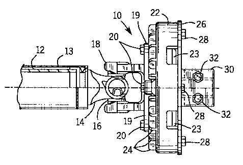
Fig. 1 illustrates a device 10 of the invention shown
coupled to a driveline 12. The driveline 12 may be any
type of driveline, for example an industrial or an
agricultural driveline, and may be provided with a shield
or guard 13.
At one end of the driveline, a universal joint yoke 14
is secured to the driveline and i8 rotatably secured to two
arms of a universal joint cross 16, whose other two arms
are rotatably secured to yoke 18, which is part of the
lQ device 10. Yoke 18 has legs 19 (three of four are shown)
which are fixed by bolts 20 to a clutch housing 22 which
has cooling fins 24 on its front side and is covered on its
back side by cover plate 26, which is secured to the
housing 22 by bolts 28.
Hub 30 is preferably In~rn~lly splined as shown at 31
to mate with the splines on a shaft to be connected to the
hub 30 and may be slotted as shown at 33 and provided with
bolts 32 for clamping it to the shaft to fix it axially,
for example for clamping it to the implement gearbox or
input shaft or power take-off shaft of a tractor. A keyed
connection or any other suitable rotary drive connection
may alternatively be used. Hub 30 extends through hole 34
(Fig. 2) of plate 26 and, at the inner end of hub 30, an
axially l-~t.-n~l;n~ flange 36 is formed and defines an outer
ball bearing race 38 on its inner diameter. A set screw 39
Q~13\1233~3.1
2149486
is screwed radially into flange 36 and opens into the race
38 so that balls 46 can be loaded into the race. It should
be noted that the gap at 90 ~for example, 0.0025 inches) is
preferably substantially smaller than the gaps at 91 (for
example, 0 . 012 inches) to inhibit lubricant flow past it .
The axial length of the gap 90 (for example, 0.25 inches)
and its smallness work as an effective seal, so that no
additional seal, such as an O-ring, is nPrP~ qry
An inner bearing race 40 is formed in flange 42 of
yoke 18, and grease fitting 44 in yoke 18 allows for
lubrication of the balls 46 in the raceways 38 and 40.
Accordingly, the anti-friction bearing provided by the
balls 46 in the raceways 38 and 40 allows for relative
rotation between the yoke 18 and the hub 30, while fixing
the yoke 18 and the hub 30 ~o~ethPr axially.
Radially outward of flange 36, a clutch plate 50 is
received in a slight recess on the inside axial face of the
housing 22, which locate~ the plate 50 radially. The
clutch plate 50 surrounds hub 3 0 and is provided with
facings 52 and 54 of friction material on its two axial
faces, between housing 22 and pressure plate 56. Pressure
plate 56 is biased toward clutch plate 50 by belleville
spring 60 so as to compress the plate 50 and facings 52 and
54 between the pressure plate 56 and the housing 22. Coil
Q33\12334~ . I
2149486
springs or other biasing means may also be used to bias the
plate 56.
Pressure plate 56 preferably has raised radially
extending angularly spaced ribs 57A and 57B (Figs. 2 and 4)
on its outer surface which press against the spring 60
adjacent to the inside ~ t~r of the spring 60 so as to
minimize the surfaoe area of contact between the pressure
plate 56 and the spring 60, thereby minimizing heat
transfer from the plate 56 to the spring 60. This
minimizes damage to the spring 60 from heat. Ribs 57A stop
at the inside diameter 59 of the plate 56 and ribs 57B rise
axially slightly at the inside diameter 59 to create
shoulders 63 which locate the spring 60 on its inside
diameter 61. Ribs 57B extend inward of the inside diameter
59 to create a centrifugal fan for cooling of the unit.
Also, open spaces 21 (two of four shown in Fig. 4) are ~=
def ined between the legs 19 and the housing 22 through
which air may be drawn by the fan to cool the unit.
Openings 23 are also preferably provided in the side o~ the
clutch housing 22 for cooling air flow.
On its outer perimeter, pressure plate 56 has ears 62
(Fig. 4) which extend into spaces 65 defined between
tpngues 64 formed on the inside of the housing 22 so as to
hold the housing 22 and pressure plate 56 nonrotata}~le
relative to one another, but allow them to move axially
Q'.33~12334~ . 1
214~8~
relative to one another . The f it of the ears 62 in the
spaces 65 need not be tight, 80 as to allow for liberal
manufacturing tolerances, since once the ears 62 contact
the tongues 64, they stay in that position, being
substantially held against relative rotation by the
frictional engagement of the clutch plate 50.
The inside periphery 70 of the clutch plate 50 defines
3 equiangularly spaced tangs 72 (Fig. 3 ) with angular
spaces 74 defined between the tangs 72. Three
equiangularly spaced lugs 76 are formed on the flange 36 of
hub 3 0 which extend into the spaces 74 and are of an
angular size smaller than the spaces 74 so that the hub 3 0
may be turned by approximately 60 degrees relative to yoke
18 (30 in either direction from being centered, as shown
in Fig. 4) before the lugs 76 contact the tangs 72. This
degree of angular freedom is sufficient in most cases to
allow aligning the splines of the hub 30 with the splines
of the shaft to which the hub 30 is to be connected, or, if
the opposite end of the drive-line is the last one to be
connected, the alignment can be made at that end as well.
More or less than three tangs and nestled lugs may be used
to practice the invention.
Under operation, when the device 10 is being used to
transmit torque in the operation of the driveline, the
torque is transmitted by the lugs 76 abutting the tangs 72
Q~3\1281i8 . 1
2149~
and is transmitted up to the torque value at which sllppage
occurs between the clutch plate 50 and the housing 22 and
pressure plate 56.
~ig. 5 illustrates a second embodiment of a device 100
of the invention. The device 100 has a yoke 118 which has
a radially ~ tPn~; n~ circular flange 119 . An outer bearing
race 138 is formed in the inside diameter of the flange 119
and an inner bearing race 140 is formed in the outside
diameter of hub 130. Thus, the bearing provided by balls
146 and races 138 and 140 allows angular rotation between
the hub 130 and yoke 118 while fixing them axially relative
to one another. A grease fitting (not shown) for
lubricating the bearing could be provided in the flange
119, and any suitable means, for example similar to the set
screw provided in the first ~mhori;r--lt~ could be provided,
for example through flange 119, to load the balls 146 into
the raceways 138 and 140.
A flange 151 is securely affixed to the hub 130 by
weld 153, or other suitable means, for example by being
cast or formed integrally with the hub 130. The ~lange 151
is axially symmetrical and defines two symmetrical wings
182 and 184. The wings 182 and 184 define between them
angular spaces 174. A shear pin 175 extends into one (or
both, although not shown) of the angular spaces 174 and is
positioned so as to abut one of the surfaces 177 or 179,
QB3\1283~3 . 1
21~9486
both of which are aligned along radial lines, should the
hub 13 0 be turned relative to the yoke 118 by approximately
60 degrees (30 in either direction from center) .
As shown in Figs. 5 and 6, the shear pin 175 is a bolt
which is secured to the f lange 119 by being inserted
through a hole 181 in the flange 119 and having a nut 183
securing it on the back side of the f lange 119 . A recessed
washer 185 may be provided at the head end of the bolt 175
so that when the head 187 gets sheared off due to a torque
overload condition, the metal of the flange 119 adjacent to
the head 187 is not damaged. In addition, the flange 119
may be heat treated to avoid damage to it. EIowever, as
shown in Fig. 7, the shear pin 175 could be a pin pressed
into a bore in the flange 119, with or without (as shown in
Fig. 7) a surrounding washer.
Many modifications and variations to the preferred
embodiments described will be apparent to those skilled in
the art. Therefore, the invention should not be limited to
the embo~iim~nt~ described, but 3hould be defined by the
claims which follow:
Qd3\12a34d . 1